

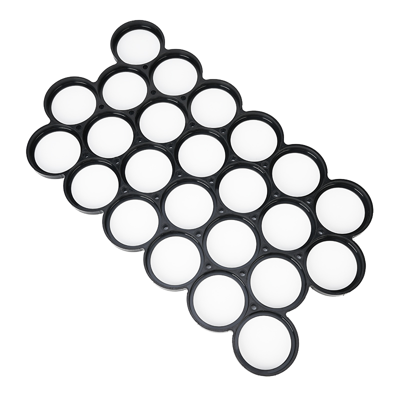
The 60160 Battery Cell Holder 4x6 Interlocking Bracket is a modular mechanical support component designed for organized cylindrical battery cell assembly. It provides a structured mounting framework for arranging large-format cylindrical cells in a compact and repeatable configuration.
The 4x6 layout represents a physical matrix containing six cell positions across one direction and four positions across the other direction, providing 24 individual cell positions when fully populated. This physical arrangement should be distinguished from the electrical series and parallel configuration of the battery pack.
The holder is particularly suitable for battery systems where accurate mechanical organization, structural reinforcement, modular assembly, and controlled cell spacing are important. Its matrix-style geometry can help establish a consistent battery architecture while the interlocking connection system allows multiple holder sections to be joined into larger assemblies.
A battery cell holder does not determine the electrical characteristics of a battery pack. Instead, it establishes the mechanical framework around which the electrical, thermal, insulation, monitoring, and enclosure systems can be developed.
The combination of a matrix hole design, central reinforcement columns, interlocking male and female connectors, and fire-retardant ABS-PC material makes this type of holder suitable for a wide range of cylindrical-cell battery projects.
What Is a 60160 Battery Cell Holder?
A 60160 battery cell holder is a molded mechanical component intended to position cylindrical cells associated with the 60160 format.
The holder typically contains individual openings or cavities into which cylindrical cells can be positioned. These cavities create a repeatable physical arrangement and help maintain the intended geometry of the battery module.
The holder may contribute to:
Cell positioning
Mechanical retention
Cell spacing
Module organization
Structural reinforcement
Inter-module connection
Assembly efficiency
Enclosure integration
The actual dimensions of a 60160 cell and the corresponding holder must always be verified before assembly. Nominal battery format numbers should not be treated as a substitute for dimensional inspection.
4x6 Battery Cell Arrangement
The 4x6 configuration provides a rectangular matrix of 24 cell positions.
This structure can be useful when designing compact battery modules with a predictable footprint.
A 4x6 matrix can simplify the physical planning of:
Cell placement
Electrical interconnections
Insulation
Temperature sensors
Wiring
Cooling paths
Module enclosure
Mechanical supports
The number 4x6 describes the physical cell arrangement only.
It does not specify whether the cells are connected in:
Series
Parallel
Series-parallel
Another electrical architecture
The electrical configuration must be established separately according to the battery system design.
Matrix Hole Design
The matrix hole design is one of the defining structural features of this battery holder concept.
Instead of positioning cells individually without a reference structure, the holder uses an organized grid of openings.
Each opening establishes a designated position for a cylindrical cell.
This matrix structure can provide several practical advantages.
Every cell cavity is located according to the same designed spacing.
Workers can place cells into predefined locations rather than manually measuring each position.
The resulting cell array remains orderly and predictable.
Regular cell positioning can simplify planning for busbars, nickel-plated strips, wires, and monitoring connections.
A consistent matrix makes it easier to estimate the overall mechanical dimensions of the battery module.
Central Reinforcement Columns
The matrix structure is complemented by central reinforcement columns.
These structural columns can increase rigidity around the holder's central region and help reduce deformation of the molded component.
Large-format Cylindrical Battery Holders can experience mechanical loads during:
Assembly
Handling
Transportation
Installation
Vibration
Equipment operation
Without adequate reinforcement, a large plastic grid may be more susceptible to bending or dimensional distortion.
Central reinforcement columns can therefore serve as important structural elements within the holder.
Function of Reinforcement Columns
Reinforcement columns may help distribute mechanical forces across the holder.
They can contribute to:
Structural rigidity
Dimensional stability
Load distribution
Reduced flexing
Improved matrix alignment
More stable cell positioning
The actual structural performance depends on the material, column geometry, wall thickness, molding quality, and overall holder architecture.
For demanding applications, mechanical testing should be performed under representative conditions.
Structural Stability of the Matrix
A battery holder must retain its intended shape during normal use.
When multiple cylindrical cells are installed, the total assembly can become relatively heavy.
The matrix structure therefore needs to maintain:
Cavity alignment
Cell spacing
Interlocking accuracy
Overall geometry
Central reinforcement elements can help support this objective.
The holder may also work together with an external enclosure or module frame to achieve the required structural strength.
Interlocking Male and Female Connectors
The interlocking male/female connector system enables multiple holder sections to be mechanically joined.
Male connectors can be designed to engage with corresponding female connectors.
This creates a modular connection between adjacent holder components.
Such a structure can support:
Modular battery layouts
Expandable assemblies
Multi-section battery modules
Flexible pack dimensions
Simplified installation
Reconfigurable prototypes
The connector geometry must provide adequate engagement without making assembly unnecessarily difficult.
Male Connector Function
The male section generally acts as the projecting portion of an interlocking connection.
It is designed to engage with the matching female section on another holder component.
A properly designed male connector should provide:
Accurate engagement
Adequate retention
Dimensional consistency
Appropriate insertion force
Reliable mechanical connection
The specific shape can vary depending on the mold and engineering design.
Female Connector Function
The female section provides the receiving geometry for the corresponding male connector.
It can help maintain alignment between adjacent holder sections.
The connection may restrict:
Lateral movement
Rotational movement
Separation
Misalignment
The exact mechanical restrictions depend on the connector design.
Advantages of Interlocking Construction
Interlocking construction provides an important advantage over a permanently fixed single-piece grid.
Individual sections can potentially be connected according to the desired module size.
This makes the system suitable for projects requiring different battery dimensions.
For example, a designer may create:
Small prototype modules
Medium battery assemblies
Large battery arrays
Extended rectangular structures
The same basic holder architecture can potentially be used across several configurations when compatible modules are available.
Modular Battery Pack Development
Battery development frequently involves changing the physical layout.
Engineers may experiment with:
Different cell counts
Different module sizes
Different enclosure dimensions
Different cooling arrangements
Different wiring routes
An interlocking holder can support faster mechanical experimentation.
Rather than redesigning a complete grid for every prototype, modular sections can be combined to produce alternative layouts.
Expandable Battery Structures
Interlocking connectors make expansion possible within the mechanical design.
A holder section can potentially be joined to another section to increase the overall cell array.
Expansion may be useful for:
Prototype development
Energy storage
Electric mobility
Robotics
Industrial equipment
Custom battery systems
Electrical and thermal design must be reassessed whenever the cell count changes.
Fire-Retardant ABS-PC Material
The holder can be manufactured from fire-retardant ABS-PC engineering material.
ABS-PC is an engineering polymer blend combining characteristics associated with acrylonitrile butadiene styrene and polycarbonate.
Depending on the exact formulation, ABS-PC can provide a useful combination of:
Mechanical strength
Impact resistance
Heat resistance
Dimensional stability
Electrical insulation
Injection molding performance
A flame-retardant grade can be selected where improved resistance to ignition and flame propagation is required.
Why ABS-PC Is Suitable for Battery Holders
Battery holders require more than simple dimensional accuracy.
They must remain mechanically stable under the environmental conditions for which they are designed.
ABS-PC can be attractive for this purpose because engineering grades can combine structural performance with relatively efficient injection molding.
Potential benefits include:
High mechanical durability
Good impact performance
Consistent molded geometry
Electrical insulation
Useful thermal properties
Complex molding capability
The exact performance must always be based on the selected material grade.
Flame-Retardant Engineering
Fire-retardant plastics are used in many electrical and electronic applications where control of material flammability is important.
A flame-retardant battery holder can provide an additional material-level safety consideration.
However, flame retardancy should never be confused with complete fire protection.
A holder made from flame-retardant material does not eliminate the risks associated with lithium-ion batteries.
Battery safety also depends on:
Cell quality
Electrical protection
BMS design
Charging control
Thermal management
Insulation
Mechanical protection
Pack enclosure
UL94 Considerations
If a specific ABS-PC material is described as UL94 V-0, the classification applies to the tested material formulation and specimen under the applicable UL 94 test conditions.
The rating should not automatically be extended to:
The entire battery pack
Other plastic components
Different material thicknesses
Modified formulations
The complete battery system
When certification is important, users should verify the actual resin grade and relevant documentation.
Heat Resistance
Large battery systems may generate significant heat during operation.
The holder material should therefore be compatible with the expected temperature range.
Temperature factors include:
Ambient temperature
Cell temperature
Charging conditions
Discharge current
Internal heat generation
Cooling performance
Enclosure temperature
The selected ABS-PC formulation should be evaluated against the expected operating environment.
Electrical Insulation Properties
Engineering plastics can provide electrical insulation between battery cells and certain surrounding components.
This can be useful in battery module construction.
However, a plastic holder alone should not be regarded as the complete insulation system.
Additional insulation may be required around:
Cell terminals
Busbars
Wiring
PCB components
Conductive enclosure surfaces
Fasteners
The complete electrical insulation design should be developed according to the battery voltage and applicable engineering requirements.
Cell Spacing and Mechanical Clearance
The matrix hole design establishes a predetermined distance between neighboring cells.
Controlled spacing can help with:
Mechanical clearance
Insulation
Wiring
Busbar routing
Thermal airflow
Assembly
The optimum spacing depends on the complete battery design.
Reducing spacing excessively can create mechanical, electrical, or thermal challenges.
Battery Pack Thermal Planning
Battery cells produce heat during operation.
The holder's geometry can influence how heat moves through the module.
Important considerations include:
Cell-to-cell spacing
Airflow
Cooling channels
Contact surfaces
Heat transfer paths
Enclosure design
The holder should be incorporated into the thermal architecture during the design stage.
Natural Air Cooling
For applications with moderate heat generation, natural convection may be considered.
A matrix holder can create predictable spaces between cells.
These spaces may assist air movement depending on the orientation and enclosure structure.
Actual thermal performance depends on the complete assembly.
Forced-Air Cooling
For higher thermal loads, forced-air cooling may be necessary.
The holder can be designed so that its matrix arrangement does not unnecessarily obstruct intended airflow.
Cooling channels should be evaluated with the complete module rather than assuming that holder spacing alone provides adequate cooling.
Battery Module Mechanical Design
A cell holder is one component within a larger battery module.
A complete module may include:
Cylindrical cells
Cell holders
Electrical interconnections
Insulation
BMS components
Temperature sensors
Wiring
Cooling components
Structural enclosure
The holder helps organize the cells while these other components address electrical, thermal, and protective requirements.
Vibration Management
Electric vehicles, drones, e-bikes, and mobile equipment can subject batteries to continuous vibration.
An interlocking holder can help keep cells arranged within the intended matrix.
The holder can reduce uncontrolled movement between adjacent cells.
However, vibration resistance must be verified at the complete module level.
The interlocking connectors, cell retention features, enclosure, and mounting structure all contribute to system performance.
Shock and Impact Considerations
Battery packs can experience mechanical shock during:
Installation
Transportation
Equipment operation
Accidental impact
The holder material and structure should be capable of handling expected mechanical conditions.
ABS-PC engineering materials can provide useful impact resistance depending on the grade.
For demanding applications, impact testing should be conducted using representative assemblies.
Dimensional Accuracy
Dimensional accuracy is essential for an interlocking battery holder.
Small deviations can influence:
Cell fit
Connector engagement
Overall module dimensions
Cell alignment
Enclosure fit
Injection molding parameters and mold quality can strongly affect dimensional consistency.
Injection-Molded Manufacturing
Battery holders with matrix cavities and interlocking connectors are well suited to injection molding.
Injection molding can integrate many features into a single component.
Possible molded elements include:
Cell openings
Reinforcement columns
Interlocking connectors
Alignment features
Retention structures
Mounting features
This manufacturing method can support repeatable production when properly controlled.
Injection Molding Advantages
Injection molding can provide:
Repeatable dimensions
High production efficiency
Complex geometry
Consistent cavity arrangement
Integrated reinforcement
Reduced assembly of individual structural components
It is particularly useful for producing large quantities of identical holder sections.
Mold Design Considerations
The mold must account for:
Material shrinkage
Draft angles
Wall thickness
Ejection
Cooling
Warpage
Connector tolerance
Cavity accuracy
Because the product contains interlocking features, connector dimensions are particularly important.
Quality Inspection
Quality inspection can focus on the mechanical characteristics of the holder.
Common inspection items include:
Overall dimensions
Cell cavity diameter
Cell cavity spacing
Connector dimensions
Reinforcement column integrity
Surface finish
Flash
Warpage
Cracks
Deformation
Functional assembly testing can verify whether adjacent holder sections interlock correctly.
Interlocking Tolerance
The male and female connectors need appropriate tolerance.
If the connection is too loose, the assembled holder may move excessively.
If it is too tight, assembly may become difficult and the connector could be damaged.
A balanced tolerance provides:
Easy assembly
Stable retention
Reliable alignment
Repeatable connection
Reasonable serviceability
Repeated Assembly and Disassembly
Modular battery holders may be assembled and disassembled during:
Prototype development
Inspection
Maintenance
Layout modification
Testing
The connector should be evaluated for wear if repeated use is expected.
Plastic clips and interlocking elements can experience fatigue after many cycles.
Battery Pack Enclosure Integration
The 4x6 holder should be designed around the dimensions of the intended enclosure.
Important factors include:
Internal enclosure length
Internal enclosure width
Holder height
Cable routing
Cooling space
Mounting points
Service clearance
A good mechanical design avoids forcing the holder into a space that is too small.
Electrical Connection Planning
A regular cell matrix can simplify electrical connection planning.
The consistent positions can help engineers determine the location of:
Busbars
Nickel strips
Conductive connectors
Wiring
Fuse links
Monitoring leads
The electrical design remains separate from the holder design.
The holder only establishes the physical framework.
BMS Integration
A battery management system can monitor and protect the battery according to its intended electrical architecture.
A structured cell holder can make the physical organization of monitoring wires easier.
Temperature sensors can also be positioned at selected points within the battery module.
The exact BMS arrangement depends on:
Cell chemistry
Cell count
Series configuration
Parallel configuration
Voltage
Current
Application requirements
Insulation and Cell Protection
Mechanical cell spacing should be combined with appropriate insulation.
Potential Insulating Materials include:
PET film
PC film
Polyimide film
Fish paper
Electrical tape
Heat-shrink tubing
Insulating pads
The correct material depends on the temperature, voltage, dielectric requirements, mechanical environment, and manufacturing process.
Applications
E-bike battery packs experience vibration, movement, and repeated cycling.
A structured cell holder can help maintain organized cell positioning inside the battery enclosure.
The holder can also simplify internal pack construction and wiring layout.
Drones require lightweight and mechanically stable battery assemblies.
A modular holder can provide a defined cell structure while supporting compact battery packaging.
Weight optimization remains important in aerial applications.
Electric vehicle battery systems can contain large numbers of cylindrical cells.
A modular holder can help organize cells into repeatable mechanical modules.
Vehicle applications require comprehensive validation for:
Vibration
Shock
Thermal management
Electrical protection
Fire safety
Environmental exposure
Energy storage systems can benefit from modular battery architecture.
Interlocking holders can potentially be used to build larger arrays from standardized mechanical sections.
This can support flexible module dimensions and organized internal structures.
Robotic systems often require compact rechargeable battery modules.
A matrix cell holder can provide mechanical stability while allowing designers to optimize battery dimensions around the robot's available space.
Portable power equipment can use cylindrical cell assemblies where mechanical organization is important.
A holder can help protect the cells from uncontrolled movement inside the enclosure.
Product Specification Reference
| Item | Description |
|---|---|
| Product Type | 60160 Battery Cell Holder 4x6 Interlocking Bracket |
| Physical Layout | 4x6 Matrix |
| Maximum Cell Positions | 24 |
| Cell Type | Cylindrical battery cells |
| Target Format | 60160 |
| Structural Design | Matrix hole structure |
| Reinforcement | Central reinforcement columns |
| Connection | Male/Female interlocking connectors |
| Material | Flame-retardant ABS-PC engineering plastic |
| Manufacturing | Injection molded |
| Structure | Modular and expandable |
| Main Function | Cell positioning and mechanical support |
| Color | Commonly black or application-specific |
| Applications | E-bike, drone, EV, energy storage and other battery systems |
Key Product Characteristics
| Feature | Functional Value |
|---|---|
| Matrix Hole Design | Creates an organized cell grid |
| Central Reinforcement Columns | Improves structural rigidity |
| Male/Female Connectors | Enables modular interconnection |
| ABS-PC Material | Provides engineering-grade mechanical properties |
| Flame-Retardant Grade | Supports improved material-level flame resistance |
| 4x6 Layout | Provides 24 physical cell positions |
| Modular Architecture | Supports expandable battery structures |
| Injection Molding | Enables repeatable production |
| Cylindrical Cell Support | Maintains organized cell positioning |
Advantages of a 4x6 Interlocking Holder
A 4x6 interlocking battery holder can offer several practical advantages.
The matrix structure provides a predefined location for every cell.
Interlocking connectors allow compatible sections to be joined.
Central reinforcement columns can help stabilize the matrix.
Injection molding allows complex structural features to be produced as an integrated component.
Predefined cell positions reduce the need for manual alignment.
Multiple sections can potentially be arranged into different physical layouts.
The holder provides a defined framework for integrating electrical and thermal components.
Design Considerations for Large Cylindrical Cells
Large-format cylindrical cells require careful mechanical planning.
The holder should consider:
Cell mass
Diameter
Length
Thermal expansion
Vibration
Impact
Enclosure loading
Connector strength
A holder that works for a small cylindrical cell cannot automatically be applied to a larger format.
Cell Fit and Tolerance
Cell fit should provide sufficient retention without creating excessive mechanical force.
An overly tight cavity can make installation difficult and potentially place unnecessary stress on the cell.
An excessively loose cavity can permit movement.
The optimal fit depends on the actual cell dimensions, holder material, manufacturing tolerance, and application conditions.
Environmental Conditions
Battery holders may be exposed to different environments.
Potential factors include:
Temperature
Humidity
Dust
Vibration
Mechanical impact
Chemical exposure
UV exposure
The material and design should be selected according to the intended environment.
Storage of Unassembled Holders
Unused holders should be stored in conditions appropriate for the polymer material.
Recommended considerations include:
Dry storage
Moderate temperature
Protection from excessive compression
Protection from direct sunlight
Clean packaging
Avoid storing components under heavy loads that could permanently deform the interlocking structures.
Installation Best Practices
Before assembly:
Inspect the holder.
Verify the intended cell format.
Measure representative cells where necessary.
Check the matrix openings.
Inspect the interlocking connectors.
Confirm the battery module design.
Prepare Insulation Materials.
Install cells according to the approved configuration.
Verify cell alignment.
Inspect the completed mechanical structure.
Do not force incompatible cells into the holder.
Maintenance Considerations
Modular construction can simplify certain maintenance activities.
Inspection may include:
Broken connectors
Deformed columns
Cracked plastic
Loose cell positioning
Damaged insulation
Wiring condition
A damaged holder should be evaluated before the battery pack is returned to service.
Safety Considerations
A battery cell holder is a mechanical component and should not be considered a complete battery safety device.
A complete battery system may require:
Appropriate cells
Correct electrical connections
BMS protection
Overcurrent protection
Thermal monitoring
Insulation
Mechanical enclosure
Appropriate charging equipment
Thermal management
The holder can support mechanical organization but cannot replace these systems.
Difference Between Mechanical Layout and Electrical Configuration
The 4x6 holder provides 24 physical cell locations.
The electrical configuration determines how those cells are connected.
For example, cells could theoretically be arranged into different series-parallel architectures while occupying a similar physical matrix.
Therefore, the holder specification should always be separated from:
Series count
Parallel count
Nominal voltage
Capacity
Energy
Current rating
This distinction is essential when documenting a battery product.
Why Modular Battery Holders Are Useful
Modular holders provide a bridge between standardized components and customized battery designs.
They can reduce the need to manufacture an entirely new mechanical structure for every battery configuration.
The same holder family can potentially support different layouts by combining compatible sections.
This approach can be especially useful during:
Product development
Engineering validation
Prototype testing
Small-batch production
Custom battery integration
Future-Oriented Battery Pack Design
As cylindrical battery systems become increasingly diversified, flexible mechanical architectures can provide practical development benefits.
A modular holder can allow engineers to adjust:
Cell count
Module dimensions
Cooling paths
Enclosure layout
Monitoring access
Structural arrangement
The modular approach is particularly useful where battery products need to be adapted for different equipment platforms.
Frequently Asked Questions
It is a modular mechanical holder designed to organize cylindrical battery cells in a 4x6 physical matrix.
A complete 4x6 matrix provides 24 physical cell positions.
It refers to the physical arrangement of four positions in one direction and six positions in another direction.
No. The 4x6 designation describes mechanical positioning and does not define the electrical series-parallel configuration.
It is a regular grid of cell openings that provides predefined positions for cylindrical cells.
They are structural elements positioned within the matrix to increase rigidity and reduce unwanted deformation.
They are complementary mechanical features that allow compatible holder sections to connect with one another.
They enable modular battery structures and can simplify expansion or reconfiguration.
A flame-retardant ABS-PC engineering plastic can be used when its mechanical and thermal properties meet the application requirements.
Engineering ABS-PC materials generally have useful electrical insulation properties, but the exact insulation performance depends on the material grade and design.
No. Flame-retardant material provides specific material-level flame performance and does not make the entire battery system fireproof.
A properly dimensioned holder can be considered for e-bike battery applications where the cell format, mechanical requirements, thermal conditions, and enclosure design are compatible.
Yes, it can be considered for suitable cylindrical-cell drone battery designs, with particular attention to weight and vibration.
It may be used as a mechanical component in suitable cylindrical-cell EV battery systems, but EV applications require comprehensive engineering validation.
Yes, modular cylindrical-cell holders can be considered for energy storage systems when the complete mechanical, electrical, thermal, and safety requirements are satisfied.
No. It is primarily a mechanical cell positioning and support component.
Depending on manufacturing requirements, customization can include dimensions, cell spacing, cavity geometry, connector design, reinforcement structure, and material grade.
Conclusion
The 60160 Battery Cell Holder 4x6 Interlocking Bracket provides a structured mechanical solution for organizing large-format cylindrical battery cells into a repeatable 4x6 matrix.
Its matrix hole design establishes consistent cell positions, while central reinforcement columns can improve the rigidity and dimensional stability of the holder. The male/female interlocking connector system adds modularity, allowing compatible holder sections to be joined into larger battery structures.
The use of flame-retardant ABS-PC engineering material can provide a combination of mechanical strength, impact resistance, dimensional stability, heat resistance, and electrical insulation when the appropriate material grade is selected. Where a specific UL94 classification is required, the actual material formulation and test documentation should be verified.
The 4x6 configuration provides 24 physical cell positions, making it suitable for compact battery modules and expandable cylindrical-cell assemblies. Because the holder establishes only the mechanical arrangement, its 4x6 structure should not be confused with an electrical 4S6P configuration or any other electrical connection scheme.
The interlocking architecture is especially valuable for modular battery development. Multiple sections can potentially be connected to create different physical dimensions, making the concept suitable for prototypes, custom battery packs, industrial equipment, e-bikes, drones, electric vehicles, robotics, and energy storage applications.
A properly designed battery holder can simplify cell alignment, enclosure integration, wiring planning, thermal layout, and mechanical assembly. Nevertheless, the holder is only one component of a complete battery system. Proper electrical protection, BMS integration, insulation, thermal management, cell selection, enclosure engineering, and applicable safety validation remain essential.
Overall, the 60160 4x6 Interlocking Battery Cell Holder combines a precision matrix structure, central reinforcement architecture, modular male/female connectors, and flame-retardant ABS-PC material to provide a flexible mechanical foundation for modern cylindrical-cell battery pack development.
This website uses cookies to ensure you get the best experience on our website.


 Phone
Phone