

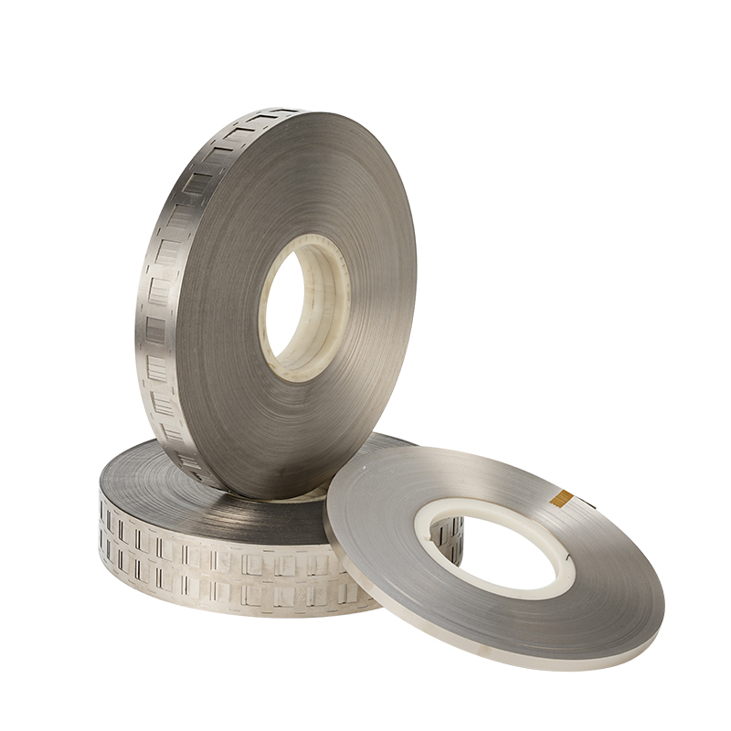
The 32650 Nickel Plated Steel Strip Battery Pack Connector is a practical conductive component designed for cylindrical lithium battery pack assembly. It is commonly used to create electrical connections between 32650 cylindrical cells and to form series, parallel, or series-parallel battery configurations. The strip combines a steel substrate with a nickel surface layer, providing a balance of mechanical strength, corrosion resistance, weldability, dimensional stability, and manufacturing cost.
The 32650 cell format is widely associated with larger cylindrical battery cells and is particularly useful in applications where relatively large cell dimensions, mechanical robustness, and pack-level energy capacity are important. During battery pack manufacturing, individual cells must be interconnected with accurately positioned conductive materials. A properly designed nickel plated steel strip can provide repeatable welding areas while maintaining the mechanical integrity required during assembly, transportation, vibration, and long-term operation.
Unlike loose wires or manually formed metal pieces, a purpose-designed battery connector strip can be manufactured in flat strips, punched configurations, perforated patterns, or preformed multi-cell layouts. This allows manufacturers to improve assembly consistency and reduce manual positioning work.
A nickel plated steel strip is not simply a piece of metal placed between cells. Its thickness, width, nickel coating, hole geometry, cell pitch, weld area, hardness, surface cleanliness, and forming accuracy can all influence the performance of the finished battery pack. For this reason, selecting the appropriate 32650 battery pack connector requires consideration of both electrical requirements and mechanical assembly conditions.
Industry specifications show that nickel-plated steel strips are available for cylindrical battery formats including 18650, 21700, 26650, and 32650. Typical battery connection strips may use thicknesses around 0.12–0.20 mm, while widths and cell spacing vary according to the cell arrangement and connector geometry.
This article provides an industry-oriented overview of 32650 Nickel Plated Steel Strip Battery Pack Connectors, including construction, materials, design principles, welding considerations, battery pack applications, dimensional selection, manufacturing methods, quality control, storage, and practical engineering considerations.
1. What Is a 32650 Nickel Plated Steel Strip Battery Pack Connector?
A 32650 Nickel Plated Steel Strip Battery Pack Connector is a shaped or flat conductive strip designed to electrically connect 32650 cylindrical battery cells.
The term "32650" generally identifies a cylindrical cell format with a nominal diameter of approximately 32 mm and a nominal length of approximately 65 mm. Actual cell dimensions can vary slightly depending on manufacturer, cell construction, protective components, terminal configuration, and mechanical tolerances.
The connector strip is installed across battery terminals and is typically joined to the cell terminals through resistance spot welding or another compatible joining process. In some pack designs, the strip may incorporate holes, slots, tabs, bridges, or other geometries to simplify alignment and welding.
The basic construction consists of:
Steel substrate
Nickel coating
Weldable connection areas
Optional punched holes
Optional positioning features
Optional preformed multi-cell geometry
The steel core provides mechanical support and dimensional stability. The nickel surface provides a suitable interface for welding and helps protect the substrate against oxidation and corrosion.
This combination makes nickel plated steel attractive for battery pack applications where a balance between conductivity, mechanical strength, processability, and material cost is required.
For example, commercially available battery connection strips are offered in SPCC nickel-plated steel, with reported nickel coating ranges and multiple thickness options for cylindrical cell applications.
2. Why Nickel Plated Steel Is Used for Battery Connections
Battery interconnection materials must satisfy several requirements simultaneously.
They need to:
Conduct electrical current.
Form reliable welds.
Remain mechanically stable.
Resist surface oxidation.
Tolerate vibration.
Maintain dimensional accuracy.
Be compatible with automated assembly.
Have suitable thickness and width.
Provide sufficient welding area.
Remain economically practical for mass production.
Pure nickel is an excellent battery interconnection material, but it can be more expensive than nickel-plated steel.
Nickel plated steel provides an alternative construction in which the steel substrate supplies mechanical strength while the nickel coating provides the external surface.
This can be useful in battery designs where current demand is moderate and where cost optimization is important.
However, nickel-plated steel should not automatically be treated as electrically equivalent to pure nickel. Material selection should be based on the required current, resistance, pulse load, weld configuration, thermal conditions, and allowable temperature rise.
Some industry product specifications explicitly distinguish nickel-plated steel from pure nickel and identify nickel-plated steel as a suitable choice for lower-power or lower-current battery applications.
3. Basic Structure of a Nickel Plated Steel Strip
The simplest structure is a steel strip covered with nickel.
The steel substrate is usually a cold-rolled steel material selected for its:
Mechanical strength
Formability
Dimensional stability
Availability
Cost efficiency
Resistance to deformation
The nickel coating forms the external surface.
The coating can contribute to:
Corrosion resistance
Surface stability
Weldability
Oxidation resistance
Contact reliability
Appearance
The exact coating thickness should be selected according to the welding process, electrical requirements, corrosion environment, and supplier capability.
Commercial specifications demonstrate that nickel coating thickness can vary substantially depending on the intended application. Some products report coating ranges from fractions of a micrometer to several micrometers.
A battery connector should therefore be evaluated as a complete material system rather than by considering only the steel substrate.
4. 32650 Battery Pack Connector Design
The design of a 32650 connector depends heavily on the battery pack configuration.
Common arrangements include:
1P
2P
3P
4P
5P
Higher parallel configurations
Series-parallel assemblies
The letter P indicates the number of cells connected in parallel within a group.
For example, a 2P configuration connects two cells in parallel. A 4P configuration connects four cells in parallel.
The connector width must increase appropriately as the number of parallel cells increases, or the design must use multiple conductive paths.
Available 32650 Nickel Strip designs commonly include several parallel configurations. Published dimensional examples include 1P widths around 14.7 mm, 2P around 47.5 mm, 3P around 82 mm, and 4P around 116.5 mm, although actual dimensions depend on the particular hole layout, cell holder, and welding pattern.
These dimensions should therefore be treated as examples rather than universal standards.
5. Cell Pitch and Connector Geometry
Cell pitch is one of the most important dimensional parameters in a battery connector.
For a 32650 battery pack, the connector must correspond to the physical distance between adjacent cells.
Typical products distinguish between different spacing conditions depending on whether a battery holder or spacer is used.
For example, some 32650 nickel strip designs use approximately 32.5 mm spacing for packs without a spacer and approximately 34.5 mm spacing for configurations using a holder.
This difference is small numerically but significant during assembly.
If the connector pitch is incorrect:
Welding points may not align.
The strip may be under mechanical stress.
Cell terminals may not be centered correctly.
The connector may buckle.
The holder may interfere with the strip.
Automated welding accuracy may decrease.
Therefore, cell pitch should always be verified against the actual battery cell, holder, insulation system, and fixture.
6. 1P 32650 Nickel Plated Steel Strip
A 1P connector is designed to accommodate a single-cell connection position.
It can be used as:
A single-cell terminal connector
A series connection component
A local reinforcement strip
A customized battery tab
A connection component in small battery assemblies
A 1P design generally requires less material than multi-cell strips.
Because it covers fewer cells, its width can remain relatively narrow.
However, narrow does not necessarily mean low importance. The weld geometry still needs to provide sufficient electrical and mechanical connection.
A 1P strip can also be used as a modular element in larger battery packs where individual connection points are assembled according to a custom circuit layout.
7. 2P 32650 Nickel Plated Steel Strip
A 2P strip is designed to connect two 32650 cells in parallel.
The two cells share a common electrical path.
This arrangement is frequently used in battery pack construction because parallel groups can increase available capacity and current capability depending on cell characteristics and system design.
A preformed 2P nickel strip can offer several assembly advantages:
Consistent cell spacing
Consistent welding locations
Faster installation
Reduced manual cutting
Better repeatability
Simplified production fixtures
Commercial 2P 32650 nickel strip products are available in both pure nickel and nickel-plated steel variants.
8. Multi-Parallel 32650 Connector Strips
Battery packs requiring larger capacity may use 3P, 4P, 5P, or higher configurations.
A larger parallel group means more cells must share the current path.
The connector design must therefore account for:
Total current
Current distribution
Weld count
Strip cross-sectional area
Thermal performance
Mechanical rigidity
Pack layout
Available space
A wider strip can provide a larger conductive path, but width alone does not determine current capacity.
The actual electrical performance depends on:
Material resistivity
Thickness
Effective cross-sectional area
Current path length
Weld resistance
Contact resistance
Temperature
Surface condition
Connection geometry
Therefore, engineers should avoid selecting a strip based solely on nominal width.
9. Thickness Selection
Thickness is one of the most important specifications of a battery connection strip.
Common nickel-plated steel battery strip thicknesses include approximately:
0.10 mm
0.12 mm
0.15 mm
0.18 mm
0.20 mm
0.25 mm
Actual availability depends on material grade and manufacturing process.
Published battery strip specifications show common thickness options around 0.12–0.20 mm, while other nickel-plated steel battery connection products are offered at 0.25 mm.
A thinner strip can provide:
Easier forming
Lower material consumption
Lower welding energy requirements in some designs
Greater flexibility
A thicker strip can provide:
Greater mechanical rigidity
Greater conductive cross-section
Increased resistance to deformation
Potentially higher current-handling capability
But thicker does not automatically mean better.
Excessive thickness can make resistance welding more difficult and may require greater welding energy.
10. Width Selection
Strip width determines the available conductive cross-sectional area and influences mechanical coverage.
The appropriate width depends on:
Number of cells
Cell spacing
Current path
Welding pattern
Terminal dimensions
Insulation clearance
Holder geometry
Standard strips may be produced in relatively narrow widths for individual cell connections, while custom multi-cell connectors can be considerably wider.
Published 32650 strip examples demonstrate multiple widths corresponding to different parallel configurations.
For custom battery packs, the strip should be designed around the actual terminal geometry rather than simply selecting a commercially available width.
11. Hole and Slot Design
Some 32650 nickel-plated steel strips include punched holes.
These holes can serve several functions.
They can:
Align the strip with battery holders.
Provide visual positioning references.
Reduce material weight.
Define welding locations.
Improve assembly repeatability.
Allow fixtures to locate the strip.
Accommodate mechanical fastening in selected designs.
Hole geometry may include:
Round holes
Square holes
Rectangular openings
Long slots
Custom punched patterns
For example, commercially available 32650 strips may distinguish hole spacing based on whether the battery pack includes a holder.
The hole should not be so close to the welding area that it weakens the strip or creates excessive current concentration.
12. Welding of 32650 Nickel Plated Steel Strip
Resistance spot welding is one of the most common methods used to attach nickel-based battery strips to cylindrical cell terminals.
The welding process uses controlled electrical current to create localized heat at the interface.
A successful weld requires appropriate control of:
Welding current
Welding time
Electrode pressure
Electrode shape
Pulse sequence
Strip thickness
Cell terminal material
Surface condition
Welding equipment
Incorrect parameters can cause:
Weak welds
Excessive heat
Strip perforation
Electrode sticking
Terminal damage
Increased electrical resistance
Surface deformation
The purpose of welding is not simply to make the strip physically stick to the cell. The weld must create a mechanically secure and electrically reliable connection without damaging the cell.
13. Weldability and Surface Cleanliness
The condition of the nickel surface strongly influences welding.
Common surface problems include:
Oil contamination
Dust
Fingerprints
Oxidation
Uneven coating
Scratches
Plating defects
A clean surface can help provide more consistent welding.
Commercial battery strip specifications sometimes emphasize oil-free or degreased surfaces because surface cleanliness can improve spot welding and soldering performance.
For automated production, surface consistency is especially important because thousands or millions of welds may be performed under similar process parameters.
14. Nickel Coating Uniformity
Nickel coating uniformity is another important factor.
An uneven coating can produce inconsistent surface behavior during welding.
Important coating characteristics include:
Thickness
Adhesion
Uniformity
Surface cleanliness
Oxidation resistance
Coverage
A coating that is too thin may provide insufficient surface protection.
A coating that is excessively thick may alter welding behavior.
The ideal coating specification depends on the battery design and welding process.
Some commercially documented nickel-plated steel strips specify coating thickness in the approximate 0.5–5 μm range, while other products provide broader customization ranges.
15. Mechanical Strength
Battery connectors are exposed to mechanical forces during:
Cell assembly
Spot welding
Pack installation
Transportation
Vibration
Shock
Thermal expansion
Maintenance
The strip must remain sufficiently stable so that it does not crack or deform under normal service conditions.
Steel provides a useful mechanical advantage compared with softer conductive metals.
The nickel coating also protects the external surface while maintaining a metallic connection interface.
Mechanical properties may include:
Yield strength
Tensile strength
Elongation
Hardness
Actual values depend on substrate grade, temper, thickness, rolling process, and heat treatment.
Published specifications for battery-grade nickel-plated steel strips show that mechanical properties can be tailored to different applications.
16. Electrical Considerations
The battery connector contributes to the overall resistance of the pack.
Even a small resistance can become important when current increases.
The approximate relationship is:
Power loss = I²R
where current is represented by I and resistance by R.
This means that increasing current can produce a disproportionately larger increase in resistive heating.
For this reason, a connector designed for a low-current application may not be suitable for a high-power battery system.
Engineers should evaluate:
Strip resistance
Weld resistance
Terminal resistance
Current distribution
Temperature rise
Continuous current
Peak current
Pulse current
The complete current path should be evaluated rather than the strip alone.
17. Thermal Performance
A battery connector produces some heat whenever current passes through it.
The amount depends on electrical resistance and current.
Thermal design becomes increasingly important when:
Current is high
Strip cross-section is small
Weld resistance is high
Ambient temperature is elevated
Cooling is limited
Multiple current paths converge
A poorly designed connector can create a local hot spot.
Possible consequences include:
Reduced battery efficiency
Insulation degradation
Increased internal temperature
Accelerated aging
Reduced connector life
Therefore, nickel strip design should be integrated with the battery pack's thermal management strategy.
18. Corrosion Resistance
Battery packs can experience humidity, condensation, environmental contamination, and temperature cycling.
Nickel plating helps protect the steel substrate from direct exposure.
A high-quality nickel coating should exhibit:
Good adhesion
Uniform coverage
Resistance to oxidation
Resistance to corrosion
Stable appearance
However, nickel plating is not a guarantee of unlimited corrosion resistance.
Cut edges, scratches, punched holes, and damaged areas can expose the underlying steel.
Therefore, manufacturing quality and pack-level environmental protection remain important.
19. 32650 Nickel Strip for Series Connections
Series connections increase voltage by connecting cells in sequence.
A connector strip used for series connections must bridge the appropriate positive and negative terminals while maintaining electrical isolation between unrelated conductive areas.
The strip layout should account for:
Cell polarity
Pack voltage
Insulation
Terminal geometry
Clearance
Creepage
Welding location
The connector should never create an unintended conductive path between cells.
This is particularly important in high-voltage battery systems.
20. 32650 Nickel Strip for Parallel Connections
Parallel connections combine cells to increase capacity and current capability.
A 2P, 3P, or 4P connector can electrically combine multiple cells.
However, cells connected in parallel should be appropriately matched.
Important factors include:
Voltage
Capacity
Internal resistance
State of charge
Cell chemistry
Age
Temperature
The nickel strip should not be used to compensate for poorly matched cells.
Good electrical design requires the cells and interconnection system to be considered together.
21. Series Parallel Battery Pack Applications
Many practical battery packs use a combination of series and parallel connections.
Examples include:
4S2P
6S2P
8S2P
10S2P
12S2P
10S4P
12S4P
13S4P
Custom configurations
In these systems, the nickel-plated steel strip serves as one part of the overall electrical architecture.
The final configuration depends on:
Required voltage
Required capacity
Maximum current
Cell characteristics
BMS design
Physical dimensions
Thermal management
22. Use in Energy Storage Battery Packs
32650 cells can be used in various energy storage assemblies.
Potential applications include:
Portable energy storage
Backup power
Small solar storage systems
Lighting systems
Emergency power supplies
Industrial battery modules
Portable equipment
Battery-powered instruments
The connector provides a compact method for establishing electrical continuity between cylindrical cells.
For energy storage applications, long-term stability is especially important because packs may remain operational for extended periods.
23. Use in Power Tools
Battery-powered tools require compact and mechanically robust battery assemblies.
Potential applications include:
Cordless drills
Portable saws
Grinding tools
Garden equipment
Portable work lights
The exact suitability of 32650 cells depends on the tool's electrical and mechanical requirements.
Where current demand is high, connector cross-section and weld design must be carefully evaluated.
24. Use in Electric Mobility
Larger cylindrical cells may be used in certain electric mobility battery systems.
Possible applications include:
Electric bicycles
Electric scooters
Light electric vehicles
Specialty vehicles
Utility mobility equipment
In these systems, connector design becomes more demanding because current levels, vibration, and thermal loads can be significant.
A nickel-plated steel connector may be appropriate for certain electrical paths, but higher-current systems may require thicker conductors, pure nickel, copper-based conductors, busbars, or other interconnection technologies.
25. Battery Pack Connector and BMS Integration
The nickel strip primarily provides the power connection between cells.
The Battery Management System performs a different function.
A BMS may monitor:
Cell voltage
Pack voltage
Temperature
Current
State of charge
Fault conditions
The nickel strip may be integrated physically with the BMS architecture through a dedicated sensing layout.
However, power paths and sensing paths should be designed separately to avoid unwanted measurement errors.
High-current paths can produce voltage drops that influence sensing accuracy.
26. Insulation Around Nickel Plated Steel Strips
Although the connector is conductive, the surrounding battery structure requires insulation.
Common Insulation Materials include:
Fish paper
PET film
Polyimide film
PC film
Adhesive insulation tape
Heat-shrink materials
Insulating spacers
The insulation should prevent accidental contact between:
Adjacent cells
Nickel strips
Cell housings
Busbars
Battery enclosures
BMS components
Insulation design is particularly important around the edges and punched openings of the nickel strip.
27. Edge Quality
The edges of a stamped nickel-plated steel strip should be controlled carefully.
Poor edge quality can create:
Sharp burrs
Insulation damage
Local stress concentration
Scratches on cell surfaces
Assembly difficulties
Precision stamping can reduce burr formation and improve repeatability.
For battery pack applications, dimensional accuracy is not merely cosmetic. A poorly formed strip can interfere with insulation and cell positioning.
28. Stamping and Forming
Nickel-plated steel strips can be processed using:
Precision stamping
Punching
Slitting
Roll forming
Progressive dies
Laser cutting for selected prototypes
Custom forming
High-volume battery manufacturing generally benefits from precision tooling because repeatability is important.
The tooling should maintain:
Hole position
Strip width
Cell pitch
Tab dimensions
Edge quality
Flatness
Precision manufacturing can reduce assembly variation and improve welding consistency.
29. Roll Material and Preformed Connectors
32650 nickel-plated steel strip can be supplied in different formats.
These include:
Continuous rolls
Cut lengths
Individual stamped pieces
Multi-cell connector sheets
Preformed battery tabs
Custom punched strips
Roll material is convenient for automated feeding and high-volume production.
Preformed strips can reduce assembly time where the battery configuration is standardized.
The best format depends on production volume and automation level.
30. Custom 32650 Battery Connector Design
Custom connector design may involve modifying:
Thickness
Width
Length
Hole spacing
Hole shape
Welding area
Cell pitch
Parallel configuration
Tab geometry
Surface treatment
Custom design is especially useful when standard battery strips do not match the exact pack geometry.
Before manufacturing, engineers should confirm:
Cell dimensions
Holder dimensions
Terminal dimensions
Polarity
Current requirements
Welding method
Insulation thickness
Required clearances
31. Battery Holder Compatibility
A battery holder changes the mechanical spacing between cells.
This is why the same 32650 connector may not be suitable for both holder and non-holder configurations.
Published 32650 connector specifications commonly distinguish approximately 32.5 mm and 34.5 mm spacing according to the presence of a spacer or holder.
The correct connector should therefore be selected only after confirming the actual mechanical arrangement.
32. Nickel Plated Steel Versus Pure Nickel
Nickel plated steel and pure nickel are both used for battery connections, but they have different characteristics.
Nickel plated steel generally offers:
Good mechanical strength
Lower material cost
Suitable weldability
Good corrosion resistance
Practical formability
Pure nickel generally offers:
Higher nickel content
Different electrical resistance characteristics
Excellent corrosion resistance
Established battery welding behavior
Higher material cost
The choice should be based on the application's current requirements and manufacturing process.
A common mistake is selecting pure nickel or nickel-plated steel solely according to price.
The correct decision requires evaluation of the entire battery system.
33. When Nickel Plated Steel May Be Appropriate
Nickel plated steel can be considered when:
Current demand is moderate.
Cost optimization is important.
Good mechanical strength is required.
Resistance welding is used.
Corrosion resistance is needed.
Standard cylindrical cells are used.
High-volume stamping is required.
It may be less suitable when the current path requires very low resistance or extremely high continuous current.
In such cases, alternative conductor materials or larger cross-sectional areas may be appropriate.
34. Current Capacity Should Not Be Estimated From Thickness Alone
One of the most important engineering considerations is that there is no universal current rating based only on strip thickness.
For example, two strips with the same thickness can behave differently because they have different:
Width
Material
Coating
Length
Weld configuration
Cooling conditions
Current path
Temperature limits
Current capacity should be validated through electrical and thermal testing.
A useful engineering approach is to test:
Initial resistance.
Voltage drop under load.
Temperature rise.
Weld strength.
Continuous-current performance.
Peak-current performance.
35. Contact Resistance
Total connection resistance can include:
Strip resistance
Weld resistance
Interface resistance
Terminal resistance
Connector resistance
Even if the strip itself has low resistance, poor welding can dominate the total resistance.
This is why welding quality control is essential.
A battery pack should be evaluated as a complete electrical network rather than treating the strip material as an isolated component.
36. Weld Pull Testing
Mechanical weld testing can help verify connection quality.
A pull test evaluates the force required to separate the strip from the terminal.
Depending on the welding process, failure modes may include:
Strip tearing
Weld nugget failure
Interface separation
Terminal deformation
The desired failure mode and acceptance criteria should be defined according to the battery design and applicable manufacturing standards.
37. Electrical Resistance Testing
Resistance testing can identify defective connections.
Testing may be performed:
After welding
During production
During sample inspection
During final battery testing
Unusually high resistance may indicate:
Poor weld
Surface contamination
Incorrect welding parameters
Damaged coating
Insufficient welding energy
Misalignment
Resistance testing can therefore be integrated into quality control.
38. Visual Inspection
Visual inspection can identify:
Scratches
Oxidation
Plating defects
Burrs
Deformation
Incorrect hole positions
Surface contamination
Automated vision systems can be used for high-volume production.
This is particularly useful when connector geometry is complex.
39. Dimensional Inspection
Important dimensional characteristics include:
Thickness
Width
Length
Hole diameter
Hole spacing
Cell pitch
Flatness
Tab length
Edge position
Precision inspection is important because a small dimensional error can become significant when many cells are assembled into a large battery module.
40. Flatness and Alignment
A flat connector should remain sufficiently planar before welding.
Excessive curvature can cause:
Uneven contact
Welding inconsistency
Mechanical stress
Assembly difficulty
Flatness can be affected by:
Rolling
Slitting
Stamping
Punching
Packaging
Transportation
Proper coil handling and storage can help preserve dimensional stability.
41. Packaging and Storage
Nickel-plated steel strip should be protected from:
Moisture
Dust
Chemical contamination
Excessive humidity
Mechanical damage
Recommended storage practices generally include:
Dry indoor storage
Sealed packaging when appropriate
Avoiding direct contact with corrosive materials
Protecting surfaces from scratches
Avoiding excessive compression
Surface cleanliness is particularly important before welding.
42. Manufacturing Quality Control
A quality control program for 32650 nickel-plated steel strips may include:
Check:
Steel grade
Thickness
Width
Surface condition
Nickel coating
Mechanical properties
Monitor:
Slitting accuracy
Stamping accuracy
Hole position
Burr height
Flatness
Surface contamination
Verify:
Dimensions
Coating quality
Packaging
Weldability
Mechanical performance
Electrical characteristics
43. Common Problems During Battery Pack Assembly
Several problems can occur when installing nickel-plated steel connectors.
The strip does not align with the cell centers.
Sharp edges damage insulation.
The strip separates during mechanical testing.
The cell terminal experiences excessive heat.
The connection has inadequate strength.
The strip cannot meet electrical or mechanical requirements.
Welding becomes inconsistent.
The battery pack may be electrically misconfigured.
These problems demonstrate why connector selection and process control must be performed together.
44. How to Select a 32650 Nickel Plated Steel Strip
A practical selection process can follow these steps.
Verify that the cells are actually compatible with the 32650 connector geometry.
Determine whether a holder or spacer is used.
Calculate:
Nominal current
Continuous current
Peak current
Pulse current
Choose nickel-plated steel or another conductive material according to the electrical requirements.
Consider current path, welding requirements, and mechanical strength.
Ensure sufficient conductive area and correct physical coverage.
Resistance spot welding parameters must be compatible with the strip.
Make sure the connector does not interfere with insulation components.
Build sample assemblies.
Perform mechanical, electrical, thermal, and environmental testing.
45. Recommended Engineering Verification
Before mass production, testing may include:
Weld pull testing
Electrical resistance testing
Current loading
Temperature-rise testing
Vibration testing
Shock testing
Humidity testing
Thermal cycling
Corrosion evaluation
Insulation testing
The exact testing program depends on the final battery application.
46. Advantages of a 32650 Nickel Plated Steel Strip Battery Pack Connector
The major advantages include:
The steel substrate provides structural support.
The nickel coating protects the surface.
Nickel surfaces are commonly used in battery welding applications.
Steel maintains shape during assembly.
Nickel-plated steel can reduce material cost compared with some pure-nickel designs.
Strips can be produced in different thicknesses, widths, pitches, and configurations.
The material can be processed through stamping, punching, and slitting.
Preformed designs can simplify parallel cell connections.
47. Limitations and Engineering Considerations
Nickel-plated steel is not appropriate for every battery application.
Potential limitations include:
Higher resistance than highly conductive copper-based materials
Lower conductivity than pure copper
Coating-dependent surface behavior
Potential edge corrosion if the coating is damaged
Current limitations in high-power applications
Welding parameter sensitivity
Therefore, the material should be selected according to the actual operating conditions.
48. Importance of Battery Pack Safety
Battery interconnection components contribute to overall battery safety.
A poorly designed connector can contribute to:
Local heating
Electrical instability
Mechanical failure
Short circuits
Insulation damage
The connector should therefore be integrated with:
Cell holders
Insulation materials
BMS
Fuse systems
Enclosure
Thermal management
Welding process
Battery safety cannot be achieved by the connector alone.
49. 32650 Nickel Strip for Automated Production
Automated battery assembly requires highly consistent connector geometry.
Important characteristics include:
Uniform strip width
Consistent thickness
Accurate pitch
Stable coating
Low burrs
Consistent flatness
Reliable feeding
Roll-form nickel-plated steel can be especially useful in automated manufacturing where continuous feeding equipment is employed.
Preformed strips can also reduce positioning time.
50. Future Development of Battery Connection Materials
Battery interconnection technology continues to evolve.
Important development directions include:
Lower-resistance conductors
Higher-current connectors
More precise stamping
Integrated sensing structures
Lightweight interconnection
Advanced coatings
Automated inspection
Laser welding
Intelligent manufacturing
As battery packs become more compact, the connector must perform more functions within a smaller physical space.
51. Difference Between Connector Strip and Busbar
A connector strip is typically a relatively thin conductive component used to connect individual cells or small groups of cells.
A busbar is generally designed for larger current paths and can have greater thickness or cross-sectional area.
The distinction is not always absolute.
A large nickel strip can function as a current-carrying busbar in certain low-to-moderate current applications.
The correct terminology depends on the battery architecture.
52. Difference Between Nickel Strip and Nickel Tab
A nickel strip is usually a continuous or preformed conductive material.
A nickel tab generally refers to a smaller terminal extension or connection tab.
Both may serve similar electrical functions, but their physical configurations are different.
For 32650 cylindrical cells, nickel strips are frequently used as cell-to-cell interconnection materials.
53. Difference Between Nickel Plated Steel and Nickel Coated Copper
Nickel-plated steel uses steel as the substrate.
Nickel-coated copper uses copper as the substrate.
Copper provides much higher electrical conductivity, while steel provides greater mechanical strength and lower material cost.
Therefore:
Steel-based connectors can be suitable for moderate current paths.
Copper-based conductors can be advantageous for high-current applications.
Material selection should follow electrical and mechanical requirements.
54. 32650 Connector for Prototype Development
For prototype battery packs, standard 32650 nickel strips can reduce development time.
Engineers can quickly test:
Cell spacing
Weld parameters
Pack layout
Insulation
Current performance
Mechanical stability
Once the design is validated, a customized stamped connector can be developed for production.
55. Customization for OEM Battery Packs
Custom 32650 connectors may be designed according to:
Cell arrangement
BMS location
Enclosure geometry
Terminal position
Welding equipment
Production volume
Electrical load
Customization can reduce unnecessary material and improve assembly efficiency.
It can also integrate holes, tabs, bridges, and positioning structures into one component.
56. Practical Design Checklist
Before purchasing or designing a 32650 Nickel Plated Steel Strip Battery Pack Connector, confirm:
Cell format
Cell diameter
Cell length
Cell pitch
Holder type
Series configuration
Parallel configuration
Continuous current
Peak current
Strip thickness
Strip width
Nickel coating
Welding method
Weld pattern
Hole pattern
Insulation clearance
Packaging format
Quality requirements
This checklist helps reduce dimensional and electrical mismatches.
57. General Reference Specifications
The following values are general industry reference ranges rather than universal standards. Actual specifications should be established according to the final battery design.
| Parameter | Typical Reference |
|---|---|
| Battery Cell Format | 32650 Cylindrical Cell |
| Substrate | Nickel Plated Steel |
| Common Steel Grade | SPCC or equivalent |
| Typical Thickness | 0.12–0.25 mm |
| Typical Nickel Coating | Application dependent |
| Connector Type | Flat, punched, preformed or custom |
| Parallel Configuration | 1P, 2P, 3P, 4P and higher |
| Typical Cell Pitch Examples | Approximately 32.5–34.5 mm |
| Welding Method | Resistance Spot Welding |
| Surface | Nickel Plated Metallic Surface |
| Processing | Slitting, Stamping, Punching |
| Packaging | Roll or Cut Piece |
| Main Application | Cylindrical Battery Pack Assembly |
Commercially documented products illustrate 0.15 mm and 0.20 mm thickness options, while 32650 layouts may use different widths and approximately 32.5 mm or 34.5 mm welding-center spacing depending on holder configuration.
58. Frequently Asked Questions
It is a nickel-coated steel conductive strip designed to connect 32650 cylindrical battery cells during battery pack assembly.
Yes. Preformed 1P, 2P, 3P, 4P and other configurations can be manufactured depending on the battery layout.
Yes, provided the connector geometry and insulation system are correctly designed for the intended series configuration.
No. Nickel-plated steel has a steel substrate covered with nickel, while pure nickel consists primarily of nickel material.
No. Thickness must be selected according to current, welding requirements, mechanical requirements, and thermal performance.
Yes. Width, thickness, pitch, hole geometry, length, welding areas, and multi-cell configuration can be customized.
Yes. Continuous roll material is commonly used for manufacturing and automated assembly.
Nickel-plated steel strips are commonly designed for resistance spot welding, but welding parameters must be validated for the exact strip and cell combination.
59. Conclusion
The 32650 Nickel Plated Steel Strip Battery Pack Connector is an important auxiliary component for cylindrical lithium battery pack manufacturing. Its combination of a steel substrate and nickel-plated surface provides a useful balance between mechanical strength, surface protection, weldability, processability, and cost.
The most important factors in selecting a connector are not simply the product name or nominal thickness. Engineers should evaluate the complete connection system, including cell pitch, connector width, strip thickness, nickel coating, welding method, current load, thermal behavior, insulation clearance, and battery configuration.
For 32650 cylindrical cells, preformed connector layouts can simplify 1P, 2P, 3P, 4P, and higher parallel configurations. Published product examples demonstrate that cell-holder arrangements can affect connector spacing, with approximately 32.5 mm and 34.5 mm configurations appearing in commercially available designs.
A properly selected nickel-plated steel connector can contribute to consistent battery assembly and reliable electrical interconnection. However, final performance should always be confirmed through application-specific welding, electrical, thermal, mechanical, and safety validation.
This website uses cookies to ensure you get the best experience on our website.


 Phone
Phone