

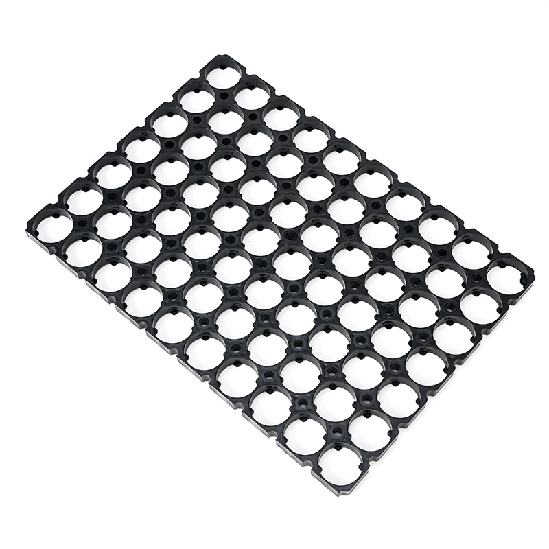
The 32650 7x10 Battery Cell Holder Mounting Bracket is a specialized structural component designed for organizing and positioning cylindrical battery cells in lithium-ion battery packs, energy storage modules, portable power systems, industrial battery assemblies, and other cylindrical-cell applications. The holder provides a controlled mechanical arrangement for cylindrical cells while helping improve assembly consistency, cell spacing, insulation separation, structural stability, and thermal-management performance.
A 7x10 configuration generally describes an array containing seven cell positions in one direction and ten positions in another direction. If every position is populated, the arrangement can accommodate up to 70 cylindrical cells. The actual number of cells used in a finished battery module depends on the electrical configuration, available enclosure space, thermal requirements, and battery architecture.
The 32650 cylindrical cell format is particularly suitable for applications that require larger cylindrical cells and robust mechanical organization. Because 32650 cells are physically larger than many commonly used cylindrical formats, their holder geometry requires appropriate opening dimensions, support structures, cell pitch, wall thickness, and reinforcement.
A well-designed 32650 battery cell holder should not simply keep cells in place. It should be considered part of the complete battery-module architecture. Its geometry can influence cell alignment, Nickel Strip installation, welding access, cooling pathways, insulation clearance, BMS wiring, module assembly, and long-term mechanical stability.
The major characteristics of a professionally designed holder include lightweight and sturdy construction, heat resistance, impact resistance, design robustness, dimensional stability, good surface gloss, and a strong heat dissipation structure. These characteristics are particularly valuable when a battery pack must combine high cell count with limited internal space.
1. Definition of a 32650 Battery Cell Holder Mounting Bracket
A battery cell holder mounting bracket is a mechanical positioning component used to maintain cylindrical battery cells in predetermined locations.
For a cylindrical-cell battery module, individual cells must be arranged with controlled spacing. If the cells are not properly supported, movement can occur during assembly, transportation, vibration, or operation.
A cell holder can provide:
Accurate cell positioning
Controlled cell spacing
Mechanical support
Electrical separation
Assembly guidance
Welding alignment
Airflow pathways
Structural reinforcement
BMS cable organization
Module integration
The holder is normally installed inside the battery enclosure and works together with other components such as nickel-plated steel strips, busbars, insulating sheets, end plates, cooling structures, wiring, and protective housings.
The holder itself is generally not the primary electrical conductor. Instead, it provides the mechanical framework required for reliable electrical interconnection.
2. Understanding the 32650 Cell Format
The designation 32650 is commonly used to identify a cylindrical battery size family.
The numerical designation generally indicates an approximate diameter and length. However, actual cell dimensions can vary according to cell manufacturer, construction, terminal design, protective sleeve, and manufacturing tolerance.
Therefore, a holder should be developed according to the actual cell dimensions rather than relying solely on the nominal cell designation.
Important dimensions include:
Cell outside diameter
Cell overall length
Positive terminal diameter
Positive terminal height
Negative terminal geometry
Insulating sleeve thickness
Cell dimensional tolerance
The holder opening should account for these variables.
A properly engineered opening allows cells to be installed efficiently while minimizing unnecessary lateral movement.
3. 7x10 Battery Cell Arrangement
A 7x10 battery cell holder generally refers to a holder designed for seven rows or columns in one direction and ten positions in the other.
This creates a potential maximum of 70 cell locations.
The arrangement can be implemented as:
Straight grid
Offset grid
Staggered configuration
Honeycomb-style arrangement
Custom series-parallel layout
The exact geometry depends on the battery pack architecture.
A rectangular 7x10 arrangement may be suitable when the battery enclosure has a conventional rectangular footprint. A modified arrangement can be developed when the enclosure contains curved edges, mounting structures, cooling components, or other internal restrictions.
4. Lightweight and Sturdy Construction
One of the most important design objectives for a battery cell holder is achieving a balance between low weight and sufficient mechanical strength.
A battery holder does not generate electrical energy, so excessive structural mass can reduce the overall system-level energy-to-weight ratio.
At the same time, the holder must be sufficiently strong to:
Keep cells aligned
Resist vibration
Support assembly loads
Prevent excessive cell movement
Maintain dimensional accuracy
Protect cell positioning during transportation
A lightweight and sturdy design can be achieved through engineering plastics combined with optimized structural geometry.
Rather than making every section thick, designers can use:
Vertical pillars
Reinforcement ribs
Curved support walls
Honeycomb structures
Strategic material distribution
Reinforced mounting points
This approach can increase stiffness while controlling material consumption.
5. Heat-Resisting Material Selection
Battery modules generate heat during charging and discharging.
The temperature near individual cells can rise significantly depending on:
Charging current
Discharge current
Cell internal resistance
Ambient temperature
Cooling system
Battery enclosure
Duty cycle
The battery holder therefore needs to maintain sufficient dimensional and mechanical stability at the expected operating temperature.
Heat-resisting engineering plastics may be selected when the battery application requires enhanced thermal performance.
Potential material families include:
ABS
PC
ABS PC blends
PP
PA
PBT
Flame-retardant engineering plastics
Other application-specific polymers
The actual material should be selected according to the complete thermal environment.
A material that performs well under normal room-temperature conditions may not provide adequate performance in a high-temperature battery module.
6. Impact Resistance
Impact resistance is important because battery modules can experience mechanical shocks during their service life.
Potential impact sources include:
Transportation
Installation
Equipment handling
Vehicle vibration
Accidental drops
Mechanical shock
Assembly operations
The holder should resist cracking around important structural areas.
These areas can include:
Cell openings
Mounting holes
Support pillars
Outer frame
Snap-fit structures
Reinforcement ribs
Impact-resistant plastic can improve the reliability of the positioning system.
However, impact resistance should always be evaluated at the complete module level rather than judging the holder as an isolated component.
7. Design Robustness
Design robustness refers to the ability of the holder structure to maintain its intended function under normal variations in manufacturing, assembly, temperature, vibration, and operating conditions.
A robust design should tolerate reasonable variation without losing its primary functions.
For a 32650 battery holder, robustness can involve:
Strong cell support
Stable mounting points
Reinforced pillars
Proper wall thickness
Controlled clearances
Adequate welding access
Stable upper and lower alignment
Resistance to deformation
Robust design is especially important in large cell arrays because small positioning errors can accumulate across multiple rows.
8. Dimensional Stability
Dimensional stability is critical for injection-molded battery holders.
The component must maintain important dimensions during:
Manufacturing
Storage
Assembly
Temperature changes
Long-term operation
Critical dimensions can include:
Cell opening diameter
Cell pitch
Row spacing
Holder height
Overall width
Overall length
Mounting-hole location
Pillar height
Poor dimensional stability can cause cells to become difficult to install or allow excessive movement after assembly.
9. Good Surface Gloss
Good surface gloss is an aesthetic and manufacturing-quality characteristic of injection-molded plastic parts.
A consistent surface can indicate good mold processing and appropriate material selection.
Surface appearance may be influenced by:
Mold surface finish
Polymer grade
Injection temperature
Mold temperature
Injection speed
Cooling conditions
Mold release behavior
For battery holders, appearance is generally secondary to mechanical and electrical performance. Nevertheless, a clean and consistent surface can be beneficial for production inspection and product presentation.
10. Strong Heat Dissipation Structure
The phrase strong heat dissipation structure should be understood primarily as a holder geometry that supports thermal pathways rather than a claim that the plastic itself is highly thermally conductive.
A well-designed holder can facilitate heat removal by maintaining controlled spaces around the cylindrical cells.
Possible features include:
Ventilation openings
Hollow pillars
Air channels
Cell-to-cell gaps
Open side structures
Cooling plate clearance
Thermal pad interfaces
The purpose is to prevent the holder from unnecessarily blocking the intended cooling route.
In an air-cooled system, the holder can support airflow around the cell surfaces.
In a liquid-cooled system, the holder may be designed around cooling plates or thermal interface components.
11. Thermal Management in 32650 Battery Packs
Thermal management is a major consideration in cylindrical battery design.
During operation, heat is generated inside the cells.
If heat is not adequately removed, excessive temperature can influence:
Battery performance
Charging behavior
Discharge capability
Cycle life
Cell consistency
System reliability
A cell holder cannot replace a complete thermal-management system, but it can support that system.
For example, the holder can maintain consistent cell spacing and preserve airflow paths.
12. Cell Spacing
Cell spacing is one of the most important dimensions of a battery holder.
Too little spacing can create problems for:
Thermal management
Insulation
Welding
Assembly
Mechanical tolerances
Too much spacing can unnecessarily increase module size.
The appropriate pitch depends on the actual battery design.
Factors include:
Cell diameter
Cooling method
Insulation thickness
Nickel strip geometry
Module enclosure
Expected temperature
Mechanical requirements
13. Cell Opening Design
The cell opening should be matched to the actual 32650 cell.
An opening that is too small can make insertion difficult.
An opening that is too large can allow excessive movement.
The design should also account for the cell's insulating sleeve.
The effective external diameter may be slightly larger than the metal cell can itself.
Therefore, cell-holder development should use actual production cells or representative samples.
14. Upper and Lower Holder Configuration
Many cylindrical battery modules use upper and lower holders.
The lower holder positions one end of the cells.
The upper holder positions the opposite end.
Together they create a more stable mechanical structure.
Depending on the battery architecture, the two holders can be:
Identical
Mirror-image designs
Functionally different designs
Integrated with other structural components
The upper holder may need additional clearance for positive terminals, while the lower holder may accommodate negative-terminal geometry.
15. Mechanical Support for Cylindrical Cells
A cylindrical cell can rotate or shift if it is not properly restrained.
A holder can provide radial positioning around the cell body.
The support geometry should prevent unnecessary movement without applying excessive pressure.
Possible structures include:
Circular openings
Partial cylindrical walls
Flexible tabs
Retaining ribs
Snap-fit features
Multi-point supports
The selected structure depends on cell tolerance and assembly requirements.
16. Electrical Insulation
Battery cell holders can contribute to electrical isolation.
Adjacent cylindrical cells can operate at different electrical potentials when connected in series.
Physical separation reduces the risk of unintended contact.
The holder material should have suitable electrical insulation characteristics.
However, a cell holder should not automatically be considered a complete electrical insulation system.
Additional materials may be required, such as:
PET film
Mylar insulation
Fish paper
Polyimide tape
PVC insulation
Heat-shrink tubing
Insulating barriers
The complete module should be evaluated for electrical safety.
17. Compatibility With Nickel Plated Steel Strip
Cylindrical cells are frequently interconnected using nickel-plated steel strips or other battery interconnection materials.
The 32650 holder should therefore be compatible with the intended connecting-strip geometry.
The design should consider:
Strip width
Strip thickness
Welding location
Cell terminal position
Electrode access
Strip routing
Holder clearance
A well-designed holder allows the connecting strip to be positioned accurately across the cell terminals.
18. Spot Welding Support
Resistance spot welding is widely used in cylindrical battery pack manufacturing.
During welding, stable cell positioning is important.
A holder can help ensure that cells remain aligned while nickel-plated steel strips are installed.
The holder should provide sufficient clearance for welding electrodes.
Potential interference areas include:
Cell terminal
Nickel strip
Welding electrode
Holder wall
Retaining ribs
The final welding process should always be validated using the actual cell, strip, welding equipment, and holder geometry.
19. Laser Welding Considerations
Some battery manufacturing processes use laser welding.
When laser welding is used, the holder should provide a suitable working area around the welding region.
Design considerations may include:
Laser access
Material compatibility
Heat exposure
Welding clearance
Optical access
Protection from unnecessary thermal loading
The holder geometry should not obstruct the intended laser path.
20. BMS Wiring Management
A battery management system requires wiring for cell monitoring and temperature sensing.
A customized cell holder can include wire-management structures.
These can include:
Cable channels
Wire clips
Sampling-wire guides
Sensor mounting points
Routing slots
BMS board supports
Good cable organization can reduce assembly complexity and help prevent wires from interfering with cell connections.
21. Temperature Sensor Installation
Temperature sensors may be positioned near selected cells.
A customized holder can provide designated sensor locations.
The objective is to maintain repeatable sensor placement.
However, sensor positioning must be based on the actual thermal design.
A sensor that is poorly positioned may not accurately represent the intended cell or module temperature.
22. Airflow Management
A battery holder can contribute to airflow management by maintaining open channels around cylindrical cells.
An effective airflow structure should consider:
Air inlet
Air outlet
Cell heat generation
Fan capacity
Flow resistance
Dust protection
Enclosure geometry
The holder should avoid creating unnecessary dead zones or blocked channels.
23. Honeycomb-Inspired Geometry
A honeycomb-style battery holder uses repeated cell openings and structural walls to create an efficient mechanical arrangement.
This type of structure can offer a useful balance between:
Mechanical rigidity
Material usage
Cell positioning
Space efficiency
Airflow
The actual performance depends on the cell diameter, wall thickness, pitch, and overall module design.
24. Staggered Cell Arrangement
A staggered arrangement offsets adjacent rows.
This can change the way cylindrical cells occupy the available space.
Potential benefits include:
Improved space utilization
Compact module design
Efficient structural distribution
Additional airflow pathways
Flexible enclosure integration
The staggered arrangement should be evaluated against the intended busbar or nickel-strip layout.
25. Straight Grid Arrangement
A straight grid places cells in aligned rows and columns.
This arrangement can simplify:
Automated assembly
Coordinate-based cell placement
Wiring
Busbar design
Module inspection
A straight arrangement may be preferred when the enclosure has a rectangular internal geometry.
26. Choosing Between Staggered and Straight Layouts
The appropriate layout depends on the complete battery system.
A staggered design can be advantageous for compact packaging.
A straight grid may simplify electrical interconnection.
The designer should evaluate:
Cell quantity
Available space
Thermal requirements
Welding method
Connecting-strip design
BMS wiring
Enclosure geometry
Assembly equipment
There is no universal arrangement suitable for every 32650 battery pack.
27. Injection Molding
Injection molding is a common manufacturing process for battery holders.
The process can produce complex repeated geometries efficiently.
A polymer is heated and injected into a mold cavity.
After cooling, the molded holder is ejected.
For a 7x10 holder, injection molding can create multiple cell openings, pillars, ribs, and mounting structures in one component.
28. Mold Design
Mold design has a major influence on the final battery holder.
Important considerations include:
Gate location
Cooling channels
Ejection system
Draft angle
Parting line
Wall thickness
Shrinkage
Warpage
Surface finish
Poor mold design can lead to:
Uneven dimensions
Warpage
Sink marks
Short shots
Flash
Internal stress
29. Wall Thickness Optimization
Wall thickness should be optimized for strength and manufacturability.
Very thin walls can reduce mechanical strength.
Very thick sections may cause:
Increased weight
Longer cooling time
Sink marks
Uneven shrinkage
Warpage
Uniform wall thickness is generally desirable where practical.
Reinforcement ribs can be used to improve stiffness without excessively increasing bulk.
30. Reinforcement Ribs
Reinforcement ribs are structural features that improve rigidity.
They can be positioned around:
Cell openings
Outer edges
Mounting points
Pillars
Connection areas
Ribs should be designed carefully to avoid molding defects.
Their thickness and height should be compatible with the selected polymer and manufacturing process.
31. Vertical Support Pillars
Vertical pillars can strengthen the holder and separate neighboring cells.
They can also contribute to airflow.
A pillar may be positioned between cell openings or around the perimeter.
The pillar dimensions depend on:
Material strength
Cell weight
Vibration level
Holder height
Module structure
Manufacturing requirements
32. Mounting Features
A mounting bracket may include mechanical features for integration into the battery enclosure.
Possible features include:
Screw holes
Bolt holes
Locating pins
Snap-fit clips
Brackets
Alignment slots
The mounting structure should be strong enough to maintain holder alignment throughout the intended service life.
33. Snap-Fit Features
Snap-fit structures can simplify battery holder assembly.
They can reduce the number of separate fasteners required.
However, snap-fit geometry should account for:
Polymer flexibility
Assembly force
Repeated installation
Temperature
Long-term stress
Fatigue
The correct design depends heavily on the selected material.
34. Dimensional Tolerance
Tolerance management becomes increasingly important as cell counts increase.
In a 7x10 array, small errors in individual cell positions can accumulate.
Critical dimensions should therefore be controlled during manufacturing.
These include:
Cell-hole diameter
Cell center distance
Row spacing
Column spacing
Holder outer dimensions
Mounting-hole position
Inspection equipment may include calipers, gauges, coordinate measuring systems, optical measurement systems, or dedicated inspection fixtures.
35. Thermal Expansion
Both plastic holders and battery cells can experience dimensional changes as temperature changes.
The coefficient of thermal expansion of the selected polymer should be considered during design.
If the clearance is too small, thermal expansion can increase mechanical stress.
If the clearance is too large, cell movement can increase.
The correct balance should be determined through engineering analysis and prototype testing.
36. Chemical Resistance
Battery holders may encounter various substances during manufacturing and operation.
Potential exposure can include:
Cleaning agents
Oils
Adhesives
Humidity
Industrial chemicals
Battery-related contaminants
The actual polymer should be checked against the chemicals present in the intended environment.
General chemical resistance claims should not replace application-specific compatibility testing.
37. Flame Retardant Materials
Some battery applications require enhanced resistance to ignition and flame propagation.
Flame-retardant polymer grades can be considered for these applications.
However, flame-retardant plastic is only one element of battery safety.
Complete battery safety depends on:
Cell chemistry
Electrical protection
BMS operation
Thermal management
Module design
Venting
Insulation
Fire-propagation control
38. Surface Quality
Good surface quality is useful for production inspection.
A high-quality molded holder should generally be free from obvious:
Cracks
Flash
Burn marks
Contamination
Deformation
Short shots
Major sink marks
Surface quality can also influence assembly because rough or damaged areas may interfere with cell insertion.
39. Cell Insertion
The cell holder should allow efficient cell insertion.
For manual assembly, the openings should be easy to identify and access.
For automated assembly, the openings should provide repeatable positioning.
The insertion force should be controlled so that cells can be installed without unnecessary mechanical stress.
40. Automated Battery Assembly
Automated production places additional demands on cell holders.
The holder should provide:
Repeatable dimensions
Clear reference surfaces
Stable positioning
Machine-accessible geometry
Consistent cell openings
Welding clearance
Reliable stacking
A customized holder can be designed around the specific automation equipment.
41. Manual Assembly
For prototype and low-volume production, battery cells may be inserted manually.
A well-designed 32650 holder can simplify this process.
Useful features include:
Clear cell openings
Orientation marks
Accessible edges
Stable base
Appropriate clearance
42. Battery Holder for Energy Storage
The 32650 battery holder can be used in energy-storage battery systems where large numbers of cylindrical cells are arranged into modules.
Potential applications include:
Residential energy storage
Commercial energy storage
Industrial backup power
Solar energy storage
Portable power systems
Communication backup systems
The holder helps maintain an organized mechanical structure within the enclosure.
43. Battery Holder for Industrial Equipment
Industrial battery systems often operate for long periods and may experience mechanical vibration.
A durable holder can help maintain cell alignment.
The material should be selected according to:
Operating temperature
Mechanical load
Chemical environment
Vibration
Service life
44. Battery Holder for Portable Power Stations
Portable power systems require compact internal packaging.
A lightweight 32650 cell holder can help organize cylindrical cells while minimizing structural weight.
The holder may also be customized with cable-management structures.
45. Battery Holder for Electric Mobility
Cylindrical battery modules may be used in various electric mobility applications.
These systems can experience:
Vibration
Shock
Temperature changes
Humidity
Long operating cycles
The holder therefore needs to work together with the enclosure, insulation, welding connections, and thermal-management system.
46. Mechanical Vibration
Continuous vibration can cause gradual movement of internal components.
Potential consequences include:
Cell movement
Connection fatigue
Wire movement
Insulation wear
Mechanical loosening
A properly designed holder reduces unnecessary cell movement.
Vibration testing should be performed on the complete battery module where appropriate.
47. Shock Resistance
A robust holder can help maintain cell arrangement during mechanical shock.
Rounded transitions can reduce stress concentrations.
Reinforced mounting points can help prevent structural failure.
The final shock resistance depends on the entire battery module.
48. Design for Manufacturability
A good battery holder design should be suitable for efficient manufacturing.
Design for manufacturability can involve:
Consistent wall thickness
Suitable draft angles
Practical mold complexity
Appropriate material selection
Reduced undercuts
Efficient ejection
Stable cooling
A design that performs well mechanically but is difficult to mold may not be commercially practical.
49. Design for Assembly
The holder should also be designed around the assembly process.
The design should consider:
Cell insertion direction
Upper and lower holder installation
Nickel strip placement
Welding access
BMS wiring
Insulation installation
Enclosure assembly
This integrated approach can reduce production problems.
50. Design for Inspection
Critical dimensions should be measurable.
Inspection-friendly features can include:
Reference surfaces
Accessible mounting holes
Clearly defined datum points
Consistent openings
Production inspection should focus on dimensions that directly influence battery assembly.
51. Prototype Development
Prototype development allows the holder to be tested before mass production.
A prototype can reveal:
Incorrect cell clearance
Cell movement
Assembly difficulties
Welding interference
Thermal restrictions
Wiring conflicts
Enclosure interference
Actual 32650 cells should be used for meaningful validation whenever possible.
52. Mechanical Testing
Mechanical testing can evaluate:
Cell retention
Holder strength
Mounting strength
Impact resistance
Vibration resistance
Snap-fit durability
Structural deformation
Test methods should reflect the intended application.
53. Thermal Testing
Thermal testing can evaluate holder behavior under representative battery temperatures.
Possible evaluations include:
High-temperature exposure
Low-temperature exposure
Thermal cycling
Dimensional change
Structural deformation
The complete battery module should also be evaluated because holder performance is only one part of system-level thermal behavior.
54. Environmental Testing
Depending on the application, environmental tests may include:
Humidity
Temperature cycling
Chemical exposure
Mechanical vibration
Mechanical shock
Long-term aging
Testing should use the actual production material.
55. Quality Control During Production
Quality control can be divided into several stages.
Verify the polymer grade and relevant material characteristics.
Monitor molding parameters and production consistency.
Check important functional dimensions.
Identify molding defects.
Use representative cells to verify fit and alignment.
56. Common Battery Holder Problems
The cell becomes difficult to insert.
The cell can move excessively.
Thermal and insulation clearance may be compromised.
The battery module becomes unnecessarily large.
The holder may deform under vibration.
The holder may shift inside the enclosure.
The welding electrode may contact the holder.
The component may become unnecessarily heavy.
The holder may soften, crack, or deform under actual operating conditions.
57. Selecting the Right Plastic
Material selection should be based on actual requirements.
For applications emphasizing impact resistance, polycarbonate or suitable PC blends may be considered.
For applications requiring a balance between processability and mechanical properties, ABS or ABS PC materials may be appropriate.
For applications requiring specific high-temperature performance, specialized engineering polymers may be considered.
For applications requiring enhanced flame resistance, certified flame-retardant grades may be evaluated.
No single plastic is ideal for every battery holder.
58. Why Engineering Plastics Are Suitable
Engineering plastics offer several advantages for battery holders.
They can provide:
Low density
Electrical insulation
Mechanical strength
Chemical resistance
Heat resistance
Design flexibility
Injection-molding compatibility
Their ability to form complex structures is particularly valuable for cell holders.
59. Lightweight Structural Engineering
A lightweight holder can be developed using structural optimization.
Instead of increasing material thickness everywhere, designers can place material where it contributes most to stiffness.
Examples include:
Perimeter ribs
Vertical pillars
Cross supports
Reinforced mounting zones
Honeycomb walls
This can provide a useful strength-to-weight ratio.
60. Strong Structural Framework
The holder should form a stable framework around the cell array.
The outer frame can provide:
Overall rigidity
Mounting support
Alignment
Protection against deformation
Internal pillars can support individual cell positions.
Together, these structures create a three-dimensional mechanical framework.
61. Space Efficiency
Battery manufacturers often need to maximize the number of cells within a limited enclosure.
A carefully designed 7x10 holder can improve internal organization.
However, space efficiency should not eliminate necessary clearance.
There must still be adequate room for:
Cooling
Insulation
Welding
Wiring
Mechanical tolerances
62. Battery Pack Safety Considerations
The cell holder contributes to battery-pack safety by supporting mechanical organization and electrical separation.
However, it is only one component of the overall safety system.
A complete battery pack may require:
Cell protection
BMS
Fuse protection
Insulation
Thermal management
Structural protection
Venting
Monitoring
Appropriate electrical connections
63. Integration With Insulation Materials
A 32650 cell holder can work together with insulation components.
For example, insulating sheets can be positioned between cell groups and conductive structural components.
Potential materials include:
PET
Polycarbonate
Fish paper
Polyimide
The holder geometry can include clearance for these materials.
64. Integration With Busbars
Some battery modules use busbars instead of simple nickel strips.
A holder should provide adequate clearance for the selected busbar architecture.
The designer should consider:
Busbar thickness
Busbar position
Fastening points
Welding locations
Insulation requirements
BMS connections
65. Integration With Battery Enclosures
The outer dimensions of the holder should match the available enclosure space.
Important considerations include:
Internal enclosure width
Internal enclosure height
Mounting points
Cooling components
Wiring space
Service access
A customized holder can be developed around an existing enclosure.
66. Customization Options
A customized 32650 battery holder can include:
Custom cell count
Custom 7x10 arrangement
Custom hole diameter
Custom cell pitch
Custom holder height
Custom outer dimensions
Custom mounting holes
Custom cable channels
Custom reinforcement
Custom ventilation openings
Custom snap-fit structures
Custom color
Custom surface finish
Custom material grade
67. Color and Identification
Although color does not normally determine battery-holder performance, different colors can help identify:
Module versions
Production batches
Cell configurations
Assembly orientations
Positive and negative sides
Color selection should use materials compatible with the required thermal and flame-performance requirements.
68. Surface Finish
Injection-molded holders can have different surface finishes.
Possible finishes include:
Smooth
Matte
Textured
Glossy
A smooth or glossy finish may simplify visual inspection.
A textured finish may provide different handling characteristics.
The appropriate finish depends on manufacturing requirements.
69. Long-Term Durability
Long-term durability depends on:
Material
Temperature
Vibration
Mechanical stress
Chemical environment
Cell movement
Installation method
A holder should be designed so that its mechanical performance remains adequate throughout the expected service period.
70. Storage and Transportation
Finished holders should be packaged carefully.
Thin pillars and retaining structures can be damaged by excessive compression.
Packaging should protect against:
Impact
Bending
Compression
Moisture
Dust
Proper packaging helps maintain dimensional quality before assembly.
71. Procurement Considerations
When purchasing a customized battery holder, technical information should be clearly specified.
Important information includes:
Cell model
Actual cell dimensions
Number of cells
Cell arrangement
Holder material
Operating temperature
Flame requirements
Cell pitch
Opening diameter
Mounting method
Welding process
Cooling method
Required tolerances
Providing complete technical information reduces the possibility of design mismatch.
72. Sample Validation
Before mass production, sample holders should be tested with representative cells.
The validation process can include:
Cell insertion.
Cell positioning.
Holder assembly.
Nickel strip installation.
Welding access verification.
Insulation installation.
BMS wiring.
Enclosure installation.
Thermal evaluation.
Mechanical testing.
73. Production Consistency
Large-volume battery production requires consistent holder dimensions.
Production variation can affect:
Cell insertion
Welding
Module stacking
Enclosure assembly
Thermal pathways
Therefore, process control is important.
74. Application-Specific Design
A holder intended for a portable battery may prioritize low weight and compactness.
A holder for an industrial energy-storage module may prioritize durability and temperature resistance.
A holder for an automated production line may prioritize dimensional accuracy and robotic compatibility.
The best design is therefore application-specific.
75. Why 32650 Holders Require Dedicated Design
Because 32650 cells are larger than many common cylindrical cell formats, the holder must accommodate greater cell diameter and potentially greater mechanical loading.
The larger cell size affects:
Cell pitch
Holder size
Pillar spacing
Wall thickness
Cooling space
Nickel strip geometry
Module weight
A dedicated 32650 holder can therefore provide better fit and structural organization than an incorrectly adapted holder designed for another cell format.
76. 7x10 Configuration and Module Planning
A 7x10 configuration can be useful when the battery designer wants to organize 70 potential cell positions within a rectangular or customized module.
The electrical configuration might involve different combinations of series and parallel cells.
The holder itself does not determine the electrical configuration.
Instead, it provides the mechanical layout that supports the selected electrical architecture.
77. Relationship Between Cell Holder and Battery Performance
The holder does not directly determine the electrical capacity of the battery.
However, it can indirectly influence system reliability through:
Cell alignment
Cooling pathways
Welding accessibility
Mechanical stability
Insulation separation
A good mechanical structure helps other battery components perform consistently.
78. Importance of Integrated Design
The best battery holder designs are developed together with the complete battery module.
Instead of designing the holder independently, engineers should consider:
Cells
Connecting strips
Busbars
BMS
Insulation
Cooling
Enclosure
Mounting
Manufacturing process
This integrated approach can reduce interference between components.
79. Future Development of Battery Cell Holders
As cylindrical battery systems become more integrated, battery holders are evolving from simple spacers into multifunctional components.
Future designs may combine:
Cell positioning
Electrical insulation
Airflow management
Sensor positioning
Cable routing
Structural reinforcement
Automated assembly features
Fire-resistant structures
Advanced holders may therefore contribute to both mechanical and thermal architecture.
80. Conclusion
The 32650 7x10 Battery Cell Holder Mounting Bracket is a practical structural component for cylindrical lithium-ion battery modules requiring accurate cell organization, mechanical stability, electrical separation, and efficient internal packaging.
Its lightweight and sturdy construction can help reduce unnecessary structural mass while maintaining reliable cell positioning. Heat-resisting and impact-resistant materials can improve durability under demanding operating conditions. A robust structural design can provide reliable support during assembly, transportation, vibration, and long-term operation.
Important characteristics such as design robustness, dimensional stability, good surface gloss, and strong heat dissipation structure can further improve the overall quality of the holder.
The 7x10 arrangement provides up to 70 potential cell positions, although the actual battery configuration depends on the electrical design. The holder can be adapted to straight, staggered, or customized cell arrangements and can include mounting holes, reinforcement ribs, vertical pillars, airflow openings, cable channels, and other application-specific structures.
Material selection may include ABS, PC, ABS PC, PP, PA, PBT, or specialized flame-retardant engineering plastics, depending on the required mechanical, thermal, chemical, electrical, and fire-performance characteristics.
For professional battery-pack development, the holder should be designed around the actual 32650 cell dimensions rather than relying only on nominal cell specifications. Cell tolerance, insulating sleeve thickness, welding clearance, thermal expansion, cell spacing, BMS wiring, nickel strip geometry, and enclosure dimensions should all be considered during development.
A properly engineered 32650 7x10 Battery Cell Holder Mounting Bracket can provide a stable foundation for cylindrical battery modules and help manufacturers achieve more organized, repeatable, lightweight, durable, and production-friendly battery-pack structures.
This website uses cookies to ensure you get the best experience on our website.


 Phone
Phone