

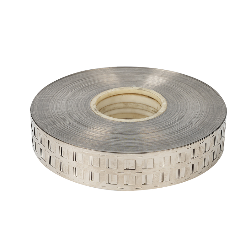
A 21700 Nickel Plated Steel Strip Battery Cell Connector is a stamped or continuous metal interconnection component designed to electrically connect cylindrical 21700 battery cells within lithium-ion battery packs, energy storage modules, power tool batteries, e-bike battery systems, portable power equipment, and other rechargeable battery assemblies.
As the 21700 cylindrical cell has become increasingly common in high-capacity battery systems, the design of the cell interconnection layer has become an important engineering consideration. A battery pack is not simply a collection of individual cells. The cells must be connected in carefully controlled series and parallel configurations, while the interconnection system must provide suitable electrical conductivity, mechanical stability, weldability, dimensional accuracy, and long-term resistance to environmental degradation.
Nickel plated steel is frequently selected for battery cell connectors because it combines a steel substrate with a nickel surface layer. The steel substrate contributes mechanical strength and dimensional stability, while the nickel surface provides a suitable welding interface and improved resistance to oxidation and corrosion compared with untreated steel. Depending on the battery design, the connector may be supplied as a straight strip, pre-cut tab, multi-cell connector, H-shaped strip, offset strip, honeycomb configuration, or another stamped geometry.
For 21700 cells, dimensional compatibility is especially important. A typical 21700 cell has a nominal diameter of approximately 21 mm, but the actual center-to-center spacing of cells in a finished pack depends on the holder, insulation structure, cell arrangement, and connector geometry. Commercial battery connection strips therefore commonly use different pitch and opening dimensions rather than relying on one universal configuration. Available examples include 21.5 mm, 22.5 mm, and 23 mm pitch configurations, while thicknesses such as 0.12 mm, 0.15 mm, and 0.20 mm are also commonly offered in the market.
This article provides an industry-oriented overview of 21700 Nickel Plated Steel Strip Battery Cell Connectors, including their structure, material selection, manufacturing processes, dimensional design, spot welding considerations, electrical performance, mechanical characteristics, corrosion behavior, pack integration, quality control, storage, handling, design considerations, and common application scenarios.
1. What Is a 21700 Nickel Plated Steel Strip Battery Cell Connector?
A 21700 Nickel Plated Steel Strip Battery Cell Connector is a thin metallic strip used to establish electrical and mechanical connections between 21700 cylindrical battery cells.
The connector is normally positioned directly over designated cell terminals and joined by resistance spot welding. Unlike conventional wire connections, a stamped metal strip provides a compact, repeatable current path that can connect multiple cells simultaneously.
The basic construction generally consists of:
Steel substrate
Nickel plating layer
Stamped or slit geometry
Weld areas
Cell openings or positioning features when required
Series or parallel connection sections
Optional formed tabs or terminal extensions
The connector can be manufactured as a continuous strip for automated processing or supplied as pre-shaped components for manual or semi-automated battery pack assembly.
For a battery pack containing multiple 21700 cells, the connector geometry determines how individual cells are grouped. For example, a parallel connector can join the positive or negative terminals of several cells, while another connector may link two adjacent parallel groups in series.
The connector therefore performs two functions simultaneously:
Electrical interconnection
Mechanical attachment to the cell terminals
This dual function makes connector design important to the reliability of the complete battery pack.
2. Why 21700 Cells Require Specialized Connection Strips
The 21700 cylindrical cell format differs from smaller cylindrical formats such as 18650 in physical dimensions and typical application requirements.
A connector designed for an 18650 pack should not automatically be assumed to fit a 21700 pack.
The larger cell diameter changes:
Cell center spacing
Strip width
Opening geometry
Welding location
Current path
Mechanical clearance
Insulation clearance
Pack layout
Commercial 21700 connection strips are therefore available in dedicated geometries. Some products use approximately 21.5 mm to 23 mm cell pitch, while multi-cell stamped configurations can have substantially greater overall widths.
The actual pitch should always be determined from the battery holder, cell spacing, pack drawing, or module architecture.
This is particularly important for automated production. A difference of even a small fraction of a millimeter can affect:
Cell alignment
Welding electrode positioning
Connector registration
Insulation clearance
Assembly tolerance
Final pack dimensions
A properly engineered 21700 Nickel Plated Steel Strip Battery Cell Connector is therefore a dimensional component rather than simply a piece of conductive metal.
3. Basic Structure of Nickel Plated Steel Battery Strip
The most common construction consists of a steel strip with a nickel coating on one or both surfaces.
The steel core provides the structural body of the connector.
The nickel coating provides the outer working surface.
A simplified structure can be understood as:
Nickel Layer / Steel Substrate / Nickel Layer
The exact coating structure depends on the manufacturing process and product specification.
The steel substrate may be selected for:
Tensile strength
Formability
Thickness consistency
Stamping performance
Dimensional stability
Cost efficiency
The nickel layer may be selected for:
Weldability
Corrosion resistance
Surface stability
Electrical contact behavior
Resistance to oxidation
Some commercial battery strips are manufactured from SPCC or DC01-type steel substrates with nickel plating. Examples available in the market include 0.12 mm, 0.15 mm, and 0.20 mm thickness configurations.
4. Nickel Plated Steel Versus Pure Nickel
One of the most important decisions in battery interconnection design is choosing between nickel plated steel and pure nickel.
Pure nickel provides excellent corrosion resistance and is widely used in battery interconnect applications. However, pure nickel can have a substantially higher material cost.
Nickel plated steel combines a lower-cost steel substrate with a nickel surface.
The choice depends on:
Required current
Connector thickness
Welding characteristics
Pack architecture
Corrosion requirements
Mechanical requirements
Material cost
Manufacturing process
Nickel plated steel is especially attractive when the connector must provide mechanical strength while maintaining a nickel surface suitable for spot welding.
However, material selection should not be based solely on price.
A connector must be evaluated according to the complete electrical and mechanical system.
The designer should consider:
DC resistance
Heat generation
Continuous current
Pulse current
Weld nugget quality
Nickel coating adhesion
Steel substrate thickness
Connector length
Current path width
Thermal environment
A thinner strip may be easy to weld but may not provide sufficient current-carrying capability for a high-current application.
Conversely, an excessively thick strip may require substantially greater welding energy and may increase the risk of damaging the cell terminal.
5. Main Advantages of 21700 Nickel Plated Steel Strip Battery Cell Connectors
Spot welding is one of the most common ways to attach battery connection strips to cylindrical cells.
A nickel-plated surface can provide a suitable interface for resistance welding when the strip thickness, plating condition, electrode geometry, pressure, current, and welding time are properly matched.
Commercial 21700 nickel plated steel strips are specifically marketed for spot-welding applications and are available in different thicknesses and cell-spacing configurations.
The steel substrate provides substantially more structural strength than an extremely thin soft metal foil.
This can help the connector withstand:
Pack assembly
Handling
Vibration
Mechanical shock
Thermal expansion
Connector routing
Stamping operations
Mechanical strength is particularly useful in battery packs where the connector also acts as a structural interconnection element.
Nickel plating helps protect the steel substrate from environmental exposure.
The plating can improve resistance against:
Humidity
Oxidation
Surface contamination
General atmospheric corrosion
However, the quality of the plating is important.
If stamping or cutting exposes the underlying steel at an edge, that exposed area may have lower corrosion resistance than the plated surface. Some commercially available stamped nickel plated strips specifically warn that cut edges may be unplated and therefore more susceptible to rust in humid environments.
This is one reason why battery connector storage and environmental control should not be ignored.
6. Electrical Conductivity and Current Path Design
The purpose of a battery cell connector is not merely to create physical contact.
It must carry electrical current safely.
The current-carrying capability depends on multiple variables, including:
Strip thickness
Strip width
Effective cross-sectional area
Material resistivity
Strip length
Connection geometry
Number of parallel strips
Weld resistance
Cell internal resistance
Ambient temperature
Cooling conditions
A wider or thicker connector generally provides a larger conductive cross section, but increasing dimensions does not automatically guarantee better pack performance.
The connector should be designed as part of the complete electrical path.
For example, a connector connecting several cells in parallel may carry a different current distribution from a connector joining two high-current series groups.
Current density may become concentrated around:
Narrow necks
Slots
Stamped holes
Bends
Weld zones
Connector transitions
Therefore, the narrowest portion of the connector may become the thermal bottleneck.
7. 21700 Battery Cell Connector Geometry
The geometry of the connector is often customized for a specific cell arrangement.
Common configurations include:
Straight strip
Single-cell strip
2P connector
3P connector
4P connector
Multi-parallel connector
H-shaped connector
Honeycomb connector
Offset connector
Bracket-free connector
Pre-cut tab
Custom stamped busbar
Market examples show 21700 strips using approximately 22.5 mm cell spacing and overall widths around 27 mm to 30.5 mm for certain two-cell configurations. These dimensions are application-specific rather than universal standards.
The exact geometry should therefore be specified using an engineering drawing.
8. Cell Pitch and Dimensional Accuracy
Cell pitch is one of the most important dimensions for a 21700 connector.
Pitch refers to the center-to-center distance between adjacent cell positions.
For example, a 21700 connector may be designed around:
21.5 mm pitch
22.5 mm pitch
23 mm pitch
depending on the battery holder and pack design.
A connector with the wrong pitch can result in:
Misalignment
Uneven welding
Mechanical stress
Poor terminal coverage
Insulation interference
Difficulty during automated assembly
For this reason, procurement specifications should not simply state:
“21700 Nickel Strip”
Instead, the specification should identify:
Cell format
Cell pitch
Number of parallel cells
Strip thickness
Strip width
Connector length
Hole dimensions
Welding zones
Material
Plating
Tolerance
9. Thickness Selection
Nickel plated steel battery strips can be supplied in different thicknesses.
Common market examples include:
0.10 mm
0.12 mm
0.15 mm
0.18 mm
0.20 mm
0.25 mm
Commercial product listings for 21700 battery strips commonly show 0.12 mm, 0.15 mm, and 0.20 mm options.
Thickness affects both electrical and welding performance.
A thicker strip generally provides:
Higher cross-sectional area
Greater mechanical strength
Potentially lower resistance for the same width and length
But it may also require:
Higher welding energy
Greater electrode force
More precise welding parameter control
A thinner strip generally offers:
Easier welding
Lower material usage
Easier forming
But it may have:
Lower mechanical strength
Higher current density
Greater sensitivity to overheating
Therefore, thickness should be selected according to actual current and welding requirements rather than using the thickest available strip.
10. Spot Welding of 21700 Nickel Plated Steel Strip
Spot welding is a resistance welding process in which electrical current passes through the connector and cell terminal while mechanical pressure is applied by electrodes.
Heat is generated primarily at the electrical resistance of the contact region.
A successful weld creates a localized welded nugget between the connector and the cell terminal.
Important welding variables include:
Welding current
Welding time
Electrode pressure
Electrode tip diameter
Pulse configuration
Number of pulses
Strip thickness
Surface condition
Cell terminal construction
The optimal settings depend on the actual material combination and equipment.
There is no universal welding parameter suitable for every 21700 connector.
11. Welding Quality
A good battery connector weld should provide:
Adequate mechanical attachment
Stable electrical connection
Consistent weld nugget
Limited heat input to the cell
No excessive splash
No severe indentation
No uncontrolled deformation
No insulation damage
Weld consistency is especially important in large battery packs.
One poor weld can create:
Higher local resistance
Local heating
Uneven current distribution
Mechanical instability
Potential long-term reliability problems
For production applications, weld quality should therefore be monitored through process control and appropriate inspection methods.
12. Welding Energy and Cell Protection
A lithium-ion cell is a heat-sensitive electrochemical device.
Excessive welding energy can transfer heat toward the cell interior.
The objective is therefore not simply to create the strongest possible weld.
The objective is to create an adequate weld while controlling thermal exposure.
Important considerations include:
Short welding duration
Controlled current
Proper electrode pressure
Correct electrode tip condition
Suitable strip thickness
Proper welding location
Adequate cooling between weld cycles
The welding process should be validated on the exact cell model and connector design being used.
13. Electrode Design
The welding electrode is an important part of the connection system.
Electrode condition can affect:
Contact resistance
Current distribution
Weld nugget diameter
Surface indentation
Heat generation
Welding repeatability
Electrode tips can gradually become contaminated or deformed during repeated production.
If electrode condition changes, the same machine settings may produce different weld results.
Therefore, production lines should establish electrode inspection and maintenance procedures.
14. Surface Cleanliness
Surface contamination can reduce welding consistency.
Potential contaminants include:
Oil
Grease
Dust
Metal particles
Oxide residues
Packaging debris
Fingerprints
Manufacturing residues
Some commercially marketed nickel-plated battery strips are specifically described as degreased or oil-free to support cleaner welding.
Clean handling is therefore important from manufacturing through final battery assembly.
15. Stamping and Forming
Many 21700 battery connectors are produced using precision stamping.
Stamping can create:
Cell openings
Slots
Positioning features
Weld tabs
H-shaped patterns
Offset patterns
Honeycomb patterns
Parallel connection sections
Precision stamping allows multiple cell connections to be integrated into one component.
This can reduce assembly time compared with manually cutting and positioning individual strips.
The stamping process should control:
Dimensional tolerance
Burr height
Edge quality
Flatness
Hole position
Strip width
Surface damage
16. Burr Control
Burrs are an important consideration for stamped battery connectors.
Sharp burrs can potentially damage:
Cell insulation sleeves
Fish paper
PET insulation
Polyimide tape
Battery holders
Protective films
Wiring insulation
A high-quality connector should therefore have controlled edges.
Burr height requirements should be defined according to the insulation system and pack architecture.
Edge quality is especially important when the connector is positioned close to the cylindrical cell body.
17. H-Shaped 21700 Nickel Strip
An H-shaped battery connector is designed to connect multiple cells while providing a controlled connection pattern.
H-shaped designs can be useful for parallel battery groups.
The geometry can provide:
Defined cell positions
Reduced manual assembly
Consistent welding locations
Integrated parallel connection
Repeatable production
Commercial examples demonstrate H-shaped 21700 nickel plated steel strip configurations, including 0.15 mm thickness and approximately 22.5 mm cell spacing.
The exact H geometry must be matched to the cell holder and terminal layout.
18. Honeycomb 21700 Connector Geometry
Honeycomb-style connectors use a patterned structure to connect multiple cylindrical cells.
The geometry can help optimize material usage while maintaining a predefined cell arrangement.
Potential advantages include:
Repeated cell positioning
Integrated multi-cell connection
Efficient pack assembly
Reduced individual strip handling
Suitable geometry for high-volume production
Honeycomb designs are commonly customized according to:
Cell pitch
Parallel count
Connector width
Welding position
Pack dimensions
19. Offset Battery Strip
Offset connectors are useful when adjacent cell rows do not align directly.
An offset geometry can accommodate:
Staggered cell arrangements
Honeycomb layouts
Irregular pack structures
Space-constrained modules
Custom cell holders
A market example describes a 21700 2P offset nickel-plated steel strip using 0.15 mm thickness and approximately 22.5 mm cell spacing.
The offset geometry should always be evaluated together with the complete cell arrangement.
20. Bracket-Free Connector Design
Some 21700 connector strips are designed without integrated cell-holder brackets.
Bracket-free strips can reduce component complexity when the pack already includes:
Plastic holders
Molded cell supports
Structural frames
Insulating plates
They can also be used in custom pack designs where the connector itself does not need to provide cell positioning.
Commercial examples describe bracket-free 21700 nickel plated steel connectors with several pitch options and thickness choices.
21. Parallel Battery Connections
In a parallel battery configuration, multiple cells are connected so that their voltage remains approximately the same while available capacity and current capability increase.
The connector must provide a common electrical path between the cell terminals.
For example, a 4P group contains four cells connected in parallel.
The connector design should ensure that current distribution is reasonably balanced.
Factors affecting current balance include:
Connector resistance
Strip geometry
Cell internal resistance
Weld resistance
Connection length
Contact arrangement
Poorly designed current paths can create unequal current sharing.
22. Series Battery Connections
In a series configuration, cells or parallel groups are connected to increase total voltage.
A series connector must link the positive terminal of one group to the negative terminal of another.
This connection may experience substantial current.
The connector should therefore have adequate:
Cross-sectional area
Weld area
Mechanical strength
Insulation clearance
The series connection should also be integrated with the BMS architecture and overall battery protection system.
23. Battery Pack Applications
21700 Nickel Plated Steel Strip Battery Cell Connectors can be used in many battery systems.
Typical applications include:
Cordless drills, saws, grinders, impact drivers, and other power tools frequently require compact high-energy battery packs.
21700 cells are increasingly used in electric bicycle battery systems where energy density and pack capacity are important.
Large parallel and series groups can be connected using stamped nickel plated steel strips.
Battery modules for backup power and renewable energy storage can use cylindrical cells arranged into large multi-cell assemblies.
Compact rechargeable equipment may use 21700 cells when greater capacity is required.
Rechargeable lighting equipment and emergency lighting systems can use cylindrical cell assemblies.
24. Battery Module Integration
The connector is only one layer of a battery module.
A complete module may contain:
21700 cells
Cell holders
Nickel plated steel connectors
Insulation sheets
Fish paper
PET film
Kapton or polyimide tape
Busbars
BMS
Temperature sensors
Fuse elements
Wiring
Housing
Cooling components
The connector must therefore be designed around the complete module.
For example, the connector must not interfere with:
BMS wiring
Temperature sensors
Cell pressure relief areas
Insulation barriers
Housing clearance
Cooling channels
25. Relationship Between Connector and BMS
The Battery Management System monitors and controls battery operation.
The nickel plated steel connector normally carries the primary cell current, while separate sensing wires monitor individual cells or groups.
The connector layout should allow the BMS wiring to be routed safely.
Poor routing can cause:
Insulation damage
Wire abrasion
Mechanical interference
Incorrect sensing connections
The BMS should never rely on an inadequately designed current connector.
26. Insulation Around Nickel Strips
The nickel strip itself is conductive.
Therefore, exposed sections must be evaluated carefully in relation to surrounding components.
Common Insulation Materials include:
Fish paper
PET insulation film
Polyimide tape
PC film
EVA foam
Insulating Gasket materials
Insulation is especially important around:
Series transition points
Pack edges
Connector bends
Metal housings
BMS wiring
Exposed connector sections
The insulation system should be designed to prevent unintended electrical contact during vibration and mechanical movement.
27. Thermal Considerations
Every electrical connection produces some heat.
Connector heating is influenced by resistance and current.
At high current, even a relatively small resistance can generate significant heat.
Therefore, designers should evaluate:
Continuous current
Peak current
Pulse duration
Ambient temperature
Connector resistance
Weld resistance
Thermal dissipation
Cooling airflow
Pack enclosure
A connector that performs adequately at low current may become unsuitable at high discharge rates.
28. Current Distribution in Multi-Cell Packs
Large battery packs can contain dozens or hundreds of cells.
The current distribution across a stamped connector may not be perfectly uniform.
Unequal current distribution can result from:
Different connector path lengths
Unequal weld resistance
Different cell internal resistance
Asymmetric busbar geometry
Uneven contact conditions
For high-current designs, electrical simulation or prototype testing can be useful.
The objective is to avoid localized current concentration.
29. Material Selection for the Steel Substrate
The steel substrate must balance strength and formability.
A suitable substrate should support:
Precision rolling
Slitting
Stamping
Forming
Welding
Dimensional stability
SPCC and DC01-type steel are among the materials used in commercial nickel plated battery strips.
The exact steel grade should be specified according to the connector's manufacturing process.
30. Nickel Plating Thickness
Nickel plating thickness can vary according to the product.
Commercial market examples show plating thicknesses around 1.5 to 2 micrometers per side for certain 21700 strips, while other nickel plated steel products list wider coating ranges.
Plating thickness affects:
Surface protection
Weldability
Corrosion resistance
Material cost
Surface durability
More plating is not automatically better.
The correct plating specification depends on the intended service environment and welding process.
31. Plating Adhesion
Nickel plating should remain firmly attached to the steel substrate.
Poor adhesion can lead to:
Peeling
Flaking
Local oxidation
Inconsistent welding
Surface contamination
Quality control can include:
Visual inspection
Adhesion testing
Thickness measurement
Surface microscopy
Bend testing
Chemical analysis when required
32. Dimensional Tolerances
For battery connectors, dimensional accuracy affects assembly reliability.
Important tolerances include:
Thickness
Width
Length
Cell pitch
Hole diameter
Hole position
Connector spacing
Flatness
Burr height
Precision stamping is commonly used to achieve repeatable battery connector geometry.
For automated assembly, tolerances should be defined based on machine capability rather than arbitrary values.
33. Flatness
A flat connector is easier to position and weld.
Excessive curvature can cause:
Uneven electrode pressure
Poor contact
Misaligned welding points
Assembly interference
Coil processing, stamping, storage, and packaging can all influence flatness.
34. Surface Appearance
A nickel plated steel strip should have a consistent surface.
Potential defects include:
Scratches
Dark stains
Plating discoloration
Pits
Blisters
Peeling
Rust
Oil contamination
Not every cosmetic difference necessarily affects performance, but visible defects can indicate manufacturing or storage problems.
35. Corrosion and Storage
Nickel plated steel strips should be stored in a controlled environment.
Recommended general conditions include:
Low humidity
Clean packaging
Limited exposure to corrosive chemicals
Protection from condensation
Protection from salt contamination
Cut edges may expose the steel substrate, making them more vulnerable to corrosion than the plated surface.
Therefore, humidity control becomes especially important for stamped products.
36. Packaging of Battery Connector Strips
Packaging should prevent:
Moisture ingress
Mechanical deformation
Surface contamination
Scratching
Connector tangling
Continuous strips can be supplied in rolls.
Pre-cut connectors can be supplied in:
Stacks
Bags
Trays
Bulk containers
Protective cartons
Commercial battery strip products are commonly supplied in rolls or packaged cartons depending on the design.
37. Continuous Roll Versus Pre-Cut Connector
Continuous roll material is suitable for:
Automated feeding
High-volume stamping
Custom cutting
Flexible connector production
Pre-cut parts are useful for:
Manual assembly
Small production batches
Repair
Prototyping
Standard battery layouts
The choice depends on production volume and assembly equipment.
38. Custom 21700 Connector Design
Custom connector manufacturing is useful when a standard strip does not match the battery architecture.
Custom dimensions may include:
Cell pitch
Strip width
Overall length
Thickness
Parallel count
Hole pattern
Offset distance
Weld tab dimensions
A professional drawing should normally define:
Material
Plating
Thickness
Tolerance
Geometry
Surface treatment
Burr requirement
Packaging requirement
39. Engineering Drawing Requirements
A complete connector drawing should identify:
Material
Thickness
Width
Length
Cell diameter
Cell pitch
Hole dimensions
Hole tolerance
Weld locations
Bend requirements
Surface treatment
Plating thickness
Edge condition
Flatness
Inspection requirements
This information minimizes misunderstandings between battery designers and connector manufacturers.
40. Choosing a 21700 Nickel Plated Steel Strip
When selecting a connector, evaluate the following questions.
Is it:
1P?
2P?
3P?
4P?
6P?
8P?
Another configuration?
Measure the actual center-to-center distance.
Consider both continuous and peak current.
Do not select thickness only by appearance.
The connector must be compatible with the welding process.
Ensure the connector does not create clearance problems.
41. Common Selection Mistakes
One common mistake is choosing a connector based only on the term “21700.”
The 21700 designation identifies a cell format, not a universal connector geometry.
Different packs may use:
Different pitch
Different holder design
Different parallel count
Different connector widths
Different welding positions
Another common mistake is choosing the thickest strip available without considering welding parameters.
A thicker connector may increase current capability but can also change welding requirements.
A third mistake is ignoring edge quality.
Sharp stamped edges can damage insulation.
42. Nickel Plated Steel Strip for High-Volume Production
For mass battery production, repeatability is more important than simply obtaining a low material price.
Important manufacturing capabilities include:
Precision slitting
Consistent plating
Precision stamping
Automated inspection
Burr control
Dimensional measurement
Coil handling
Clean packaging
The connector should perform consistently across production lots.
43. Quality Control
A comprehensive quality program can include:
Check:
Steel grade
Nickel plating
Thickness
Width
Surface condition
Check:
Stamping accuracy
Hole position
Burr height
Flatness
Check:
Dimensions
Surface appearance
Plating adhesion
Packaging
Traceability
Check:
Weld strength
Electrical resistance
Nugget consistency
Thermal impact
44. Weld Pull Testing
Mechanical pull testing can help determine whether a welded strip has adequate attachment.
A weld that fails too easily may indicate:
Insufficient welding energy
Poor electrode contact
Surface contamination
Incorrect welding parameters
Inadequate pressure
However, excessive welding energy can also be undesirable because it can increase cell heating.
Therefore, weld testing must balance mechanical strength with thermal safety.
45. Electrical Resistance Testing
Connector resistance can be measured using appropriate low-resistance test equipment.
Testing should consider the entire electrical path:
Strip resistance
Weld resistance
Contact resistance
Terminal resistance
A low-resistance strip does not automatically mean the finished connection has low resistance.
Weld quality can significantly influence the total connection resistance.
46. Thermal Testing
Thermal testing can identify potential hot spots.
During controlled battery operation, measurements may be made at:
Connector center
Weld points
Series transitions
Narrow connector sections
Cell terminals
Thermal imaging can help identify abnormal heating.
If one connector location becomes significantly hotter than others, the design should be investigated.
47. Mechanical Vibration Considerations
Battery packs may experience vibration during:
Vehicle operation
E-bike riding
Power tool use
Industrial equipment operation
Transportation
The connector must maintain attachment under expected mechanical conditions.
The design should also prevent the strip from contacting sharp housing edges or other conductive components.
48. Thermal Expansion
Battery modules can experience temperature changes.
The steel strip, cell can, holder, insulation, and housing may have different thermal expansion behavior.
Repeated thermal cycling can therefore place mechanical stress on the connector and weld points.
Good pack design should provide appropriate mechanical tolerance and avoid unnecessary constraint.
49. Connector and Battery Holder Compatibility
The cell holder determines much of the connector geometry.
The holder should:
Maintain cell alignment
Provide insulation
Support mechanical stability
Maintain consistent pitch
The nickel strip should fit naturally over the holder without excessive force.
A mismatch can create mechanical stress before welding even begins.
50. Connector and Insulation Compatibility
The connector must work together with the battery insulation system.
Potential insulation materials include:
PET
PC
Fish paper
Polyimide
EVA
The selected material should have appropriate:
Dielectric strength
Temperature resistance
Mechanical stability
Thickness
Adhesion
51. Battery Pack Assembly Sequence
A general assembly sequence may include:
Inspect cells.
Install cells into holders.
Confirm cell orientation.
Install Insulating Materials.
Position the nickel plated steel connector.
Verify connector alignment.
Perform controlled spot welding.
Inspect welds.
Install BMS connections.
Add additional insulation.
Install housing.
Conduct electrical testing.
Conduct functional testing.
The exact sequence depends on the battery architecture.
52. Cell Polarity Verification
Incorrect cell polarity is one of the most serious assembly errors.
Before welding, the polarity of every cell should be verified.
The connector geometry should also make incorrect assembly difficult where possible.
Engineering features such as:
Offset patterns
Different connector shapes
Marking
Positioning holes
can help reduce assembly errors.
53. Importance of Traceability
For professional battery manufacturing, connector traceability can include:
Material batch
Plating batch
Stamping batch
Production date
Inspection records
Packaging lot
Traceability can help identify the source of quality problems.
54. Environmental Considerations
Battery connectors are used in environments ranging from consumer products to industrial energy storage.
Environmental conditions may include:
Humidity
Temperature cycling
Vibration
Dust
Chemical exposure
Mechanical shock
The connector's surface treatment should therefore be selected according to the expected environment.
55. Nickel Plated Steel Connector for Energy Storage
Energy storage systems often contain many cylindrical cells.
The connector must support:
High cell count
Repeatable assembly
Stable current paths
BMS integration
Thermal management
Mechanical stability
Large battery systems may require customized multi-cell stamped connectors to reduce assembly complexity.
56. Connector Use in Power Tools
Power tools often demand high pulse current.
The connector should therefore be evaluated under:
High discharge current
Short-duration current peaks
Repeated charge/discharge cycles
Vibration
Elevated temperature
A connector that works in a low-current consumer device may not be appropriate for a high-power tool.
57. Connector Use in E-Bikes
E-bike battery packs experience both electrical and mechanical stress.
The connector should withstand:
Vibration
Road shock
Repeated cycling
High discharge current
Temperature variation
Mechanical support from the holder and housing is therefore as important as connector material selection.
58. Connector Use in Portable Power Stations
Portable power stations may combine many cells to achieve higher energy capacity.
A multi-cell connector system can reduce the number of individual assembly operations.
However, large packs require careful consideration of:
Current distribution
Thermal management
BMS layout
Fuse design
Insulation
Mechanical protection
59. Connector Use in Custom Battery Packs
Custom battery pack designers often select stamped nickel plated steel strips because the connector can be manufactured according to a specific cell layout.
Custom geometry can integrate:
Multiple cells
Series links
Parallel links
Welding areas
Mounting features
This can improve assembly efficiency compared with assembling many separate pieces.
60. Surface Treatment Options
Nickel is the most common surface associated with nickel plated steel battery strips.
Additional surface requirements may include:
Bright nickel
Matte nickel
Controlled plating thickness
Oil-free surface
Cleaned surface
The surface specification should be matched to the welding process.
61. Oil-Free Battery Connector Surface
Oil contamination can affect welding.
An oil-free or cleaned surface may improve process consistency.
However, the required cleanliness level depends on the manufacturing environment.
Battery manufacturers should define acceptable contamination levels based on their welding validation.
62. Connector Length
Connector length influences:
Electrical resistance
Mechanical flexibility
Pack geometry
Current distribution
Longer conductive paths generally introduce greater electrical resistance.
Therefore, the connector should not be unnecessarily long.
At the same time, sufficient length may be necessary to accommodate:
Cell spacing
Housing geometry
Weld locations
Thermal expansion
Assembly tolerances
63. Width Selection
Connector width affects:
Current capacity
Weld area
Mechanical strength
Pack dimensions
A wider strip may provide greater cross-sectional area, but it may also occupy more space.
The optimal width depends on the battery design.
64. Battery Connector Cost Considerations
Material cost is only one component of total connector cost.
Other factors include:
Plating
Stamping
Tooling
Inspection
Packaging
Waste
Production volume
Custom geometry
A lower-cost connector may become more expensive overall if it causes:
Poor welding yield
Excessive assembly time
High rejection rates
Insulation damage
Therefore, total manufacturing cost should be evaluated.
65. Standard Versus Custom Components
Standard components are useful when:
Cell arrangement is common
Pitch matches available products
Production volume is moderate
No unusual geometry is required
Custom components are preferable when:
Cell layout is unique
Current path is specialized
Space is limited
Automated production requires special registration
Connector integration is complex
66. Automated Assembly
Automated battery production benefits from components with:
Consistent dimensions
Stable feeding
Controlled flatness
Defined orientation
Repeatable pitch
Low burrs
Roll-fed connector material can be integrated into automated stamping and feeding processes.
Pre-cut parts can also be automatically picked and placed.
67. Feeding Stability
Continuous nickel plated steel strip must feed consistently.
Potential problems include:
Coil deformation
Strip curling
Uneven width
Stamping burrs
Incorrect indexing
Precision material control improves feeding stability.
68. Packaging for Long-Term Storage
For long-term storage, battery connector strips should remain protected from:
High humidity
Condensation
Salt air
Corrosive gases
Direct contact with chemicals
Packaging should also prevent physical deformation.
69. Inspection Checklist for Buyers
Before purchasing a 21700 Nickel Plated Steel Strip Battery Cell Connector, verify:
Material
Nickel plated steel
Steel substrate specification
Nickel coating specification
Dimensions
Thickness
Width
Length
Cell pitch
Hole size
Surface
Cleanliness
Plating consistency
Corrosion condition
Geometry
1P
2P
3P
4P
Custom configuration
Manufacturing
Stamping accuracy
Burr control
Flatness
Application
Spot welding
Battery current
Pack configuration
70. Typical Reference Specification Range
The following values should be treated as general industry reference ranges rather than universal specifications.
A 21700 nickel plated steel connector may be offered with:
Material: Nickel plated steel
Substrate: SPCC or DC01-type steel
Thickness: approximately 0.12–0.25 mm
Common thickness: approximately 0.15 mm
21700 pitch: approximately 21.5–23 mm
Plating: nickel
Configuration: 1P, 2P, multi-P, H-type, offset or custom
Processing: precision stamping
Connection: resistance spot welding
Commercial listings demonstrate several of these ranges, including 0.12/0.15/0.20 mm thickness and 21.5/22.5/23 mm 21700 pitch options.
71. Why Dimensional Customization Matters
Battery packs are becoming increasingly compact.
This creates demand for connectors that fit precisely into limited spaces.
Customization can optimize:
Cell utilization
Connector length
Current paths
Welding locations
Insulation clearance
BMS routing
Housing dimensions
A precisely designed connector can therefore become an important part of overall battery pack optimization.
72. Future Development of Battery Cell Connectors
Battery cell connector technology is likely to continue evolving with battery pack architecture.
Potential development directions include:
Higher precision stamping
More complex integrated busbars
Improved plating control
Automated inspection
Lower-resistance structures
Integrated fuse features
Flexible connection structures
Lightweight conductive designs
Integrated sensing features
The connector is increasingly becoming a functional component rather than simply a metal strip.
73. Difference Between Connector Strip and Busbar
A connector strip generally connects individual cells or small groups.
A busbar typically carries current between larger electrical nodes.
However, the terms can overlap in battery systems.
A large stamped nickel plated steel component can perform both functions depending on its geometry and current rating.
In larger battery systems, copper or aluminum busbars may be used for high-current paths while nickel plated steel remains suitable for cell-level connections.
74. Difference Between Nickel Plated Steel and Nickel Tape
The term “nickel tape” can refer to different materials.
It may mean:
Pure nickel strip
Nickel plated steel strip
Nickel foil
Adhesive-backed nickel tape
For battery spot welding, the exact material must be confirmed.
A product described as “nickel strip” should not automatically be assumed to be pure nickel.
Material certification or technical documentation should identify the substrate and plating.
75. Importance of Accurate Product Naming
For an English product catalog, 21700 Nickel Plated Steel Strip Battery Cell Connector clearly communicates:
Cell format: 21700
Material: nickel plated steel
Product form: strip
Function: battery cell connection
Other useful technical descriptions include:
21700 Nickel Plated Steel Battery Connector
21700 Battery Cell Connection Strip
Nickel Plated Steel Strip for 21700 Cells
21700 Battery Spot Welding Connector
21700 Lithium Battery Nickel Strip
21700 Cylindrical Cell Connector
21700 Battery Pack Interconnect Strip
These terms describe the same general product category from different engineering perspectives.
76. Best Practices for Battery Pack Designers
Battery pack designers should:
Measure the actual cell pitch.
Confirm cell terminal geometry.
Calculate expected current.
Select suitable connector thickness.
Select suitable connector width.
Confirm welding equipment capability.
Validate welding parameters.
Check connector temperature.
Inspect weld quality.
Verify insulation clearance.
Conduct mechanical testing.
Validate the complete pack under operating conditions.
77. Final Considerations
The 21700 Nickel Plated Steel Strip Battery Cell Connector is a small component with an important role in cylindrical lithium-ion battery systems.
Its performance depends on much more than material selection.
Reliable battery interconnection requires coordinated control of:
Material
Nickel plating
Thickness
Width
Cell pitch
Stamping geometry
Burr control
Welding parameters
Electrical resistance
Mechanical strength
Corrosion protection
Insulation
Thermal management
For standard applications, commercially available 21700 connector strips may provide convenient options. For specialized battery packs, custom stamping can create geometries optimized for the exact cell arrangement.
The most appropriate connector is not necessarily the thickest, widest, or least expensive option. It is the connector that provides an appropriate balance between electrical performance, weldability, mechanical reliability, dimensional accuracy, thermal behavior, manufacturability, and total battery-pack cost.
When properly designed and validated, nickel plated steel connectors can provide a practical interconnection solution for 21700 cylindrical-cell battery packs, energy storage assemblies, power tools, e-bikes, portable power systems, and other rechargeable battery applications.
This website uses cookies to ensure you get the best experience on our website.


 Phone
Phone