

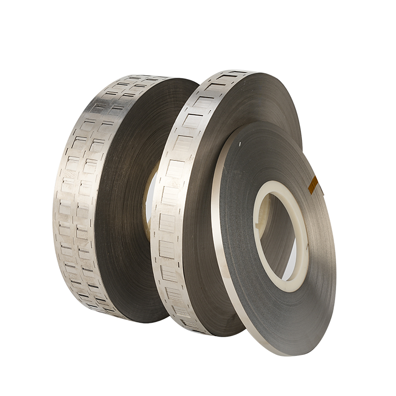
The 21700 Battery Connection Strip Spot Welding Nickel Plated Steel Strip is a specialized conductive component used to interconnect cylindrical 21700 battery cells during lithium ion battery pack assembly. It is commonly supplied as a continuous roll, pre cut strip, punched connection plate, or custom formed multi cell connector. The material is particularly useful for battery packs that require repeatable cell positioning, reliable resistance spot welding, controlled mechanical strength, and practical manufacturing cost.
The 21700 cylindrical battery format has become an important cell platform for power tools, electric mobility systems, energy storage equipment, portable power products, and other rechargeable battery applications. Compared with smaller cylindrical formats, 21700 cells provide more internal volume per cell, allowing battery designers to build packs with fewer individual cells for a given energy target. As the number and size of cells increase, the quality of the cell interconnection system becomes increasingly important.
A nickel plated steel strip consists of a steel substrate with a nickel surface layer. The steel core contributes mechanical strength and dimensional stability, while the nickel surface provides corrosion protection and a metallic surface suitable for battery connection processes. Commercially available examples for 18650 and 21700 battery assembly include thicknesses such as 0.12 mm, 0.15 mm, and 0.20 mm, with different cell pitches and parallel configurations available.
For 21700 battery packs, the connection strip is commonly joined to cell terminals using resistance spot welding. The final design must take into account strip thickness, width, cell spacing, welding parameters, current demand, thermal conditions, insulation clearance, and the mechanical arrangement of the battery module.
This article provides a comprehensive industry reference covering the structure, material characteristics, design principles, spot welding, dimensions, applications, quality control, customization, installation considerations, and engineering selection of 21700 nickel plated steel battery connection strips.
1. What Is a 21700 Battery Connection Strip?
A 21700 battery connection strip is a conductive metal component designed to electrically connect cylindrical 21700 cells.
The term 21700 generally refers to a cylindrical cell format approximately 21 mm in diameter and 70 mm in length. Actual dimensions can vary depending on cell construction, terminal design, safety components, and manufacturer tolerances.
A battery connection strip provides a controlled conductive pathway between cells.
Depending on the battery architecture, it can be used for:
Series connections
Parallel connections
Series parallel connections
Cell group interconnections
Terminal transitions
Local bus connections
Battery module connections
A strip may be manufactured as a simple rectangular metal band or as a punched component with multiple cell openings.
The latter is particularly useful when several cells are arranged in parallel.
Commercial 21700 connector designs commonly include multiple hole pitch options. Examples found in current industry listings include approximately 21.5 mm, 22.5 mm, and 23 mm configurations.
These dimensions are application examples rather than universal standards.
2. What Is Nickel Plated Steel Strip?
Nickel plated steel strip is a composite metallic material consisting of a steel substrate and a nickel coating.
The basic structure can be represented as:
Nickel Layer / Steel Substrate / Nickel Layer
Depending on the manufacturing process, nickel plating may be applied to one side or both sides.
The steel substrate provides:
Mechanical strength
Dimensional stability
Formability
Cost efficiency
Resistance to deformation
The nickel layer contributes:
Surface corrosion resistance
Oxidation protection
Metallic surface stability
Suitable welding characteristics
Improved surface durability
Some commercially documented battery strips use SPCC steel as the substrate. One current industry specification lists standard thicknesses of 0.12, 0.15, 0.18, and 0.20 mm with widths from 5 to 30 mm.
3. Why Nickel Plated Steel Is Used for 21700 Batteries
Battery interconnection materials must balance several requirements.
The material should provide:
Reliable electrical connection
Stable welding behavior
Mechanical strength
Corrosion resistance
Dimensional accuracy
Processability
Consistent surface quality
Reasonable material cost
Pure nickel is widely recognized as a battery interconnection material, but nickel plated steel can offer an economical alternative in applications where the electrical and thermal requirements are compatible with its characteristics.
The steel substrate provides greater structural rigidity than many thin pure metal strips, while the nickel coating provides the external metallic surface.
However, nickel plated steel should not automatically be considered equivalent to pure nickel.
For high current applications, designers should compare:
Electrical resistivity
Strip cross section
Current density
Temperature rise
Weld resistance
Mechanical requirements
Long term reliability
Material selection should therefore be based on the complete battery design rather than price or appearance alone.
4. Basic Construction of a 21700 Nickel Plated Steel Strip
A typical strip consists of three basic elements:
The steel core is the structural body of the strip.
It determines much of the strip's:
Tensile strength
Stiffness
Formability
Dimensional stability
The nickel layer protects the steel surface and provides a metallic interface.
Coating thickness varies by application. One published specification lists approximately 0.5–5 μm as an available nickel coating range.
The strip may then be:
Slit
Cut
Punched
Stamped
Formed
Perforated
Customized
The final geometry determines how the strip interacts with 21700 cells.
5. 21700 Battery Cell Arrangement
21700 cells can be assembled in many configurations.
Common arrangements include:
1P
2P
3P
4P
5P
6P
Higher parallel configurations
A 2P group contains two cells connected in parallel.
A 4P group contains four cells connected in parallel.
Parallel connections generally increase available capacity and current capability at the group level, while series connections increase voltage.
A battery pack may therefore be described using configurations such as:
4S2P
6S2P
8S2P
10S2P
10S4P
12S4P
13S4P
The connector geometry must correspond to the specific cell layout.
6. 21700 Battery Connection Strip for Parallel Assembly
Parallel assembly is one of the most common applications for preformed battery strips.
A multi cell strip can connect several positive or negative terminals in one operation.
Advantages include:
Consistent spacing
Reduced manual cutting
Faster assembly
Repeatable welding locations
Simplified production
Improved alignment
For example, commercially listed 21700 strips are available in 2P and multi parallel configurations with different hole pitches and thicknesses.
The number of cells that can be connected by one strip should be determined according to current requirements and thermal design.
7. 21700 Battery Connection Strip for Series Assembly
Series connections are used to increase battery pack voltage.
When cells are connected in series, the connector must bridge the correct positive and negative terminals.
The design must maintain:
Correct polarity
Adequate insulation
Appropriate clearance
Stable weld locations
Mechanical security
Incorrect series-strip geometry can create unintended electrical paths.
For this reason, series connector designs should be validated carefully before production.
8. Series Parallel Battery Pack Interconnection
Many practical battery packs combine series and parallel connections.
For example, a 10S4P battery pack contains ten series groups with four parallel cells in each group.
The nickel plated steel strip may be used at multiple levels of the architecture.
It can connect:
Cells within a parallel group
Adjacent series groups
Terminal sections
Auxiliary connection points
More complex packs require careful control of current distribution and insulation.
9. Cell Pitch
Cell pitch refers to the center to center distance between adjacent cell positions.
For 21700 battery connection strips, pitch is a critical dimensional parameter.
Common commercial examples include:
21.5 mm
22.5 mm
23 mm
Some products associate approximately 21.5 mm with Bracket free assembly, approximately 22.5 mm with fixed brackets, and approximately 23 mm with certain direct or spliced arrangements.
Another current product specification lists 21.5 mm, 22.5 mm, and 23 mm as 21700 hole pitch options.
The actual required pitch should always be measured from the battery holder and cell arrangement being used.
10. Why Cell Pitch Accuracy Matters
Incorrect pitch can cause:
Welding misalignment
Strip deformation
Cell movement
Mechanical stress
Poor insulation clearance
Production delays
In a large battery module, even a small dimensional error can accumulate across many cells.
For example, if each connector position has a slight dimensional deviation, the final position of the last cell can differ significantly from the intended location.
Precision stamping therefore becomes increasingly important as the number of cells increases.
11. Thickness Selection
Thickness affects both electrical and mechanical performance.
Common nickel plated steel strip thicknesses for cylindrical battery assembly include:
0.10 mm
0.12 mm
0.15 mm
0.18 mm
0.20 mm
0.25 mm
Current industry listings specifically show 0.12 mm, 0.15 mm, and 0.20 mm options for 18650 and 21700 battery connector strips.
A 0.15 mm strip is widely encountered in 21700 battery connection products.
However, thickness should not be selected simply because it is commonly available.
The correct thickness depends on:
Current requirement
Weldability
Mechanical strength
Strip width
Cooling
Battery architecture
12. Width Selection
Strip width determines the conductive cross sectional area together with thickness.
A wider strip may provide:
Larger current path
Greater mechanical coverage
More welding area
Better structural rigidity
However, increasing width also changes:
Material consumption
Weight
Welding requirements
Insulation layout
Available space
For custom battery packs, width should be optimized rather than maximized.
13. Continuous Roll Strip
Continuous nickel plated steel strip can be supplied in rolls.
Roll material is particularly useful for:
Automated production
High volume assembly
Continuous stamping
Custom cutting
Prototype development
Roll products can reduce repeated manual cutting operations.
A current commercial listing describes 10 m continuous nickel plated steel strip in a 0.15 × 20 mm size for 18650 and 21700 connection applications.
14. Pre Cut Battery Connection Strips
Pre cut strips are manufactured to predetermined lengths.
They are useful when:
Pack geometry is standardized
Production volume is moderate
Manual assembly is used
No continuous feeding system is required
Pre cut components can reduce preparation time.
They can also help improve dimensional consistency compared with manually cut strips.
15. Pre Punched 21700 Connector Strips
Pre punched connector strips incorporate holes or openings at predetermined positions.
These features can help:
Locate cells
Reduce material
Guide assembly
Define welding positions
Improve alignment
Interface with battery holders
A current 21700 connector listing identifies several hole pitch options and multi parallel configurations.
The shape and location of the openings must be designed carefully so that they do not weaken the strip excessively.
16. Spot Welding Principle
Resistance spot welding joins the metal strip to the cell terminal using electrical resistance and localized heat.
The general process involves:
Positioning the strip.
Positioning welding electrodes.
Applying electrode pressure.
Passing controlled electrical current.
Creating localized heating.
Forming a weld joint.
Releasing pressure.
Inspecting the connection.
The actual welding parameters depend on:
Material
Strip thickness
Nickel coating
Cell terminal
Electrode geometry
Welding machine
Current
Pulse duration
There is no single universal setting suitable for every 21700 nickel plated steel strip.
17. Spot Welding Versus Soldering
Resistance spot welding is generally preferred for many cylindrical battery interconnection applications because it can create localized joints without requiring the entire terminal area to be heated.
Some commercial battery-strip products are explicitly marketed for spot welding, while other products mention both spot welding and soldering.
However, the appropriate joining method depends on:
Cell construction
Terminal design
Connector material
Production process
Safety requirements
For battery pack manufacturing, the joining process should be validated rather than assumed.
18. Welding Current
Welding current must be matched to the strip and cell.
Too little energy can result in:
Weak welds
Incomplete bonding
High resistance
Too much energy can result in:
Excessive heat
Strip penetration
Terminal damage
Electrode sticking
Surface deformation
Published guidance for Nickel Strip Welding emphasizes that thickness and material type influence welding parameters and recommends performing test welds before production.
19. Welding Time
Welding time determines how long electrical energy is applied.
A longer pulse does not necessarily produce a better weld.
The objective is to generate enough localized heat to form an appropriate weld without unnecessarily increasing thermal exposure.
Welding time should therefore be optimized together with:
Current
Pressure
Electrode condition
Strip thickness
Cell terminal material
20. Electrode Pressure
Electrode pressure influences the contact condition during spot welding.
Insufficient pressure can cause:
Unstable contact
Excessive sparking
Inconsistent welds
Excessive pressure can:
Deform the strip
Affect current distribution
Damage sensitive components
Consistent electrode pressure is particularly important for automated welding systems.
21. Electrode Condition
Welding electrodes gradually change during production.
Possible issues include:
Contamination
Oxidation
Tip deformation
Material buildup
Uneven contact
Regular electrode maintenance can help maintain consistent welding performance.
In high volume production, electrode condition should be incorporated into the process control system.
22. Surface Cleanliness Before Welding
The strip surface should be clean and free from contamination.
Potential contaminants include:
Oil
Dust
Grease
Oxidized material
Processing residues
Some commercially documented nickel plated steel strips use degreasing or oil removal treatment before stamping.
This is important because surface contamination can change contact resistance and affect weld formation.
23. Nickel Coating Thickness
Nickel coating thickness is an important specification.
A coating must provide sufficient surface protection while remaining compatible with the welding process.
Published product information shows nickel coating ranges such as approximately 0.5–5 μm, while another 21700 Nickel Strip specification describes approximately 1.5–2 μm coating on each side.
These figures should be treated as product-specific examples rather than universal requirements.
24. Nickel Coating Adhesion
The coating must remain attached to the steel substrate during:
Stamping
Bending
Welding
Thermal cycling
Transportation
Battery operation
Poor adhesion can result in:
Flaking
Peeling
Surface exposure
Corrosion
Welding inconsistency
Therefore, coating adhesion should be included in incoming material inspection.
25. Corrosion Resistance
Nickel plating provides a protective surface over the steel substrate.
This can help protect the strip against:
Humidity
Oxidation
Atmospheric contamination
Certain corrosive environments
Some commercial nickel plated steel strips report salt spray performance as part of their product specifications.
However, corrosion resistance depends on:
Coating thickness
Coating uniformity
Edge condition
Surface damage
Environmental exposure
The battery enclosure and insulation system also contribute significantly to corrosion protection.
26. Mechanical Strength
Mechanical strength is one reason steel is used as the substrate.
The connector can experience stress during:
Stamping
Welding
Assembly
Cell expansion
Vibration
Transportation
Shock
Published specifications for SPCC nickel plated steel strips show different tensile strength ranges for soft and hard material conditions.
The appropriate mechanical condition depends on whether the connector needs flexibility or rigidity.
27. Flexibility and Formability
A battery strip should be sufficiently formable for its intended geometry.
Poor formability can lead to:
Cracks
Coating damage
Edge deformation
Dimensional instability
Soft steel conditions generally provide greater elongation and easier forming, while harder conditions may provide greater rigidity.
The correct balance depends on the connector design.
28. Electrical Resistance
The connector forms part of the battery's electrical circuit.
Its resistance depends on:
Material resistivity
Thickness
Width
Length
Temperature
Weld resistance
Contact resistance
The relationship between current and resistive heating is especially important:
Power loss = I²R
As current increases, even small increases in resistance can result in significantly higher heat generation.
Therefore, high current battery packs require careful connector design.
29. Current Distribution
A multi cell connector should distribute current as evenly as practical.
Uneven current distribution may occur because of:
Different path lengths
Unequal weld resistance
Different strip widths
Poor geometry
Cell resistance differences
This can cause some sections of the connector to carry more current than others.
For high power battery modules, current distribution should be evaluated through electrical and thermal analysis.
30. Thermal Considerations
The connection strip generates heat when current flows through it.
Heat generation can become significant when:
Current is high
Strip cross section is small
Cooling is limited
Weld resistance is high
Ambient temperature is elevated
Thermal testing should measure the temperature rise of:
Strip
Weld area
Cell terminal
Adjacent insulation
The objective is to ensure that the connection does not become an unacceptable thermal hotspot.
31. 21700 Battery Pack Insulation
The nickel strip is conductive, so insulation is essential.
Typical Insulation Materials include:
Fish paper
PET film
Polyimide film
PC film
Adhesive insulating tape
Insulating spacers
The insulation must prevent unintended electrical contact.
Particular attention should be given to:
Strip edges
Punched holes
Weld locations
Cell holders
Series connection points
32. Edge Quality
Stamped battery strips should have controlled edges.
Excessive burrs can damage:
PET insulation
Fish paper
Cell sleeves
Adhesive materials
Precision stamping and controlled tooling can reduce burr formation.
Current commercial specifications emphasize burr-free or smooth edges for battery strip applications.
33. Hole Geometry
Hole dimensions affect:
Cell alignment
Mechanical strength
Material weight
Welding accessibility
Holder compatibility
A hole that is too small may interfere with assembly.
A hole that is too large may reduce the mechanical integrity of the strip.
Therefore, hole diameter and pitch should be optimized together.
34. Bracket and Holder Compatibility
A 21700 battery pack may use a plastic cell holder or spacer.
The holder determines the physical distance between cells.
This is why different connector pitches exist.
For example, commercial 21700 strips can be found with 21.5 mm, 22.5 mm, and 23 mm pitch options.
The correct pitch should be selected according to the actual cell holder rather than relying solely on the nominal 21700 cell format.
35. Misaligned Connector Designs
Some battery connector strips are intentionally offset or misaligned.
An offset configuration can be useful where:
Cells are staggered
Pack space is limited
Adjacent connections need different positions
A custom series parallel architecture is required
Commercial examples include 21700 2P offset strips with approximately 22.5 mm cell spacing.
Offset geometry should be designed around the actual battery layout.
36. Single Row Battery Connection
Single row strips are relatively simple.
They can be used for:
Small battery packs
Single parallel groups
Series bridges
Prototype assemblies
The main advantages are:
Simple geometry
Easy installation
Low material consumption
Flexible layout
37. Double Row Battery Connection
Double row strips can connect two rows of cells.
They can improve assembly efficiency by reducing the number of individual pieces required.
Double row designs require careful attention to:
Cell pitch
Row spacing
Weld locations
Insulation
Mechanical stability
38. Multi Row Connection Strips
Larger battery modules may require multi row connectors.
These can be designed as:
3P
4P
5P
6P
Custom configurations
The larger the connector, the more important:
Flatness
Dimensional accuracy
Current distribution
Welding sequence
Mechanical stability
become.
39. Connection Strip for Energy Storage Systems
21700 cells are used in various energy storage products.
Potential applications include:
Portable power stations
Residential energy storage
Backup battery systems
Solar energy storage
Industrial battery modules
Communication backup systems
Energy storage systems often operate for long periods, making connector reliability important.
The connector should be evaluated under:
Continuous load
Thermal cycling
Humidity
Vibration
Long duration operation
40. Connection Strip for Power Tools
21700 cells are increasingly useful in high performance portable tools.
Applications can include:
Cordless drills
Impact drivers
Grinders
Saws
Garden tools
Outdoor equipment
Power tools can generate substantial current pulses.
Therefore, the connector must be selected based on actual peak and continuous current requirements.
41. Connection Strip for Electric Bicycles
Electric bicycles commonly use cylindrical cell assemblies.
A 21700 nickel plated steel connection strip may be used for cell-to-cell interconnection.
Important considerations include:
Vibration
Shock
Continuous current
Peak current
Thermal management
Pack enclosure
Insulation
The strip should be validated under realistic operating conditions.
42. Connection Strip for Portable Power Stations
Portable power stations require compact and reliable battery modules.
The connector must fit within:
Cell holder
Insulation system
BMS layout
Enclosure
Cooling structure
Preformed connector strips can simplify assembly and reduce manual positioning.
43. Connection Strip for Electric Mobility
Electric mobility applications can impose demanding electrical and mechanical requirements.
The battery interconnection system may experience:
High current
Repeated vibration
Mechanical shock
Temperature cycling
Long operating periods
For high power applications, engineers should compare nickel plated steel with pure nickel, copper based busbars, or other conductor solutions.
44. Nickel Plated Steel Versus Pure Nickel
Nickel plated steel and pure nickel should be evaluated separately.
Advantages may include:
Strong steel core
Good mechanical rigidity
Lower material cost
Suitable surface for welding
Good formability
Corrosion protection
Potential advantages include:
High nickel content
Established battery interconnection performance
Good corrosion resistance
Different electrical characteristics
Neither material is universally superior.
The correct material depends on the application.
45. Nickel Plated Steel Versus Copper
Copper has significantly higher electrical conductivity than steel.
Therefore, copper can be advantageous for high current paths.
However, copper introduces other engineering considerations, including:
Welding compatibility
Cost
Mechanical properties
Surface treatment
Connection to different metals
Nickel plated steel can be attractive where moderate current, mechanical strength, and economical manufacturing are priorities.
46. Connection Strip and Busbar Design
A thin nickel strip is usually intended for cell interconnection.
A larger busbar is generally used for higher current pathways.
However, the distinction can depend on the application.
A properly sized nickel plated steel strip can function as a local bus conductor in some battery systems.
High current designs often require greater cross-sectional area.
47. Custom 21700 Nickel Plated Steel Strip
Custom manufacturing can modify:
Thickness
Width
Length
Pitch
Hole diameter
Hole pattern
Parallel configuration
Offset geometry
Welding tabs
Surface treatment
Custom connectors can reduce the need for manual assembly and improve production consistency.
48. Stamping Process
Battery connection strips are commonly manufactured using precision stamping.
Typical processes include:
Coil feeding
Straightening
Punching
Forming
Slitting
Inspection
Cleaning
Packaging
Precision tooling determines:
Hole location
Pitch
Width
Tab dimensions
Edge quality
49. Slitting Process
Continuous strip material may be slit from wider metal coils.
Slitting must maintain:
Width accuracy
Edge quality
Flatness
Surface integrity
Poor slitting can create sharp burrs.
For battery applications, burr control is especially important because the strip is installed close to thin insulation layers.
50. Cleaning Process
Cleaning removes:
Oil
Grease
Dust
Processing residue
A clean strip can provide more stable welding.
Some current product specifications explicitly mention degreased or oil-free treatment for battery connector strips.
51. Surface Inspection
Surface inspection can identify:
Plating scratches
Pinholes
Oxidation
Discoloration
Contamination
Uneven coating
For high volume production, automated visual inspection may be used.
52. Dimensional Inspection
Important dimensions include:
Thickness
Width
Length
Pitch
Hole diameter
Hole position
Row spacing
Flatness
Burr height
One current industry specification reports thickness tolerance around ±0.002 mm and width tolerance around ±0.02 mm for a particular product range.
Such values are product-specific and should not be treated as universal industry tolerances.
53. Mechanical Testing
Mechanical testing may include:
Tensile testing
Bend testing
Peel testing after welding
Fatigue testing
Vibration testing
The purpose is to verify that the strip maintains integrity during assembly and operation.
54. Weld Strength Testing
A welded connection should be mechanically evaluated.
Possible testing methods include:
Peel testing
Pull testing
Shear testing
The exact test method depends on the connection geometry.
A good weld should provide adequate mechanical strength without damaging the cell terminal.
55. Electrical Resistance Testing
Resistance testing can identify:
Poor welds
High contact resistance
Surface contamination
Inconsistent connection quality
Testing can be performed at:
Material level
Weld level
Cell group level
Pack level
56. Temperature Rise Testing
Temperature-rise testing is particularly important for high-current battery packs.
Testing should consider:
Continuous current
Peak current
Ambient temperature
Cooling method
Strip thickness
Weld configuration
The test should monitor both the connector and adjacent cell terminal.
57. Thermal Cycling
Battery packs experience temperature changes during operation.
Thermal cycling can cause expansion and contraction of different materials.
Potential failure mechanisms include:
Coating degradation
Weld fatigue
Mechanical stress
Delamination
Insulation movement
Thermal cycling tests can help evaluate long-term reliability.
58. Vibration Resistance
Battery packs used in:
Electric vehicles
Electric bicycles
Power tools
Outdoor equipment
can experience continuous vibration.
The connector should remain securely attached.
Vibration testing can reveal:
Weld fatigue
Strip cracking
Mechanical loosening
Insulation damage
59. Storage Requirements
Nickel plated steel strips should generally be stored in a clean, dry environment.
Storage should minimize exposure to:
Moisture
Dust
Chemicals
Salt
Excessive humidity
Packaging should also prevent:
Scratching
Crushing
Bending
Contamination
60. Handling Before Welding
Before welding:
Inspect the strip.
Check the coating.
Confirm dimensions.
Remove contamination if necessary.
Verify cell polarity.
Confirm cell pitch.
Position the strip accurately.
Test welding parameters.
These steps can reduce production defects.
61. Common Welding Problems
Possible causes include insufficient energy, poor surface condition, or incorrect electrode pressure.
Possible causes include excessive welding energy or inappropriate electrode settings.
Can occur when the welding energy is too high for the strip thickness.
May result from contamination, electrode wear, inconsistent pressure, or dimensional variation.
Usually related to incorrect pitch or inadequate positioning.
62. Common Connector Design Problems
The strip does not align with the cells.
The strip cannot achieve the required electrical or mechanical performance.
The current path becomes too restrictive.
The connector interferes with insulation or adjacent components.
The edge damages insulation.
The strip cannot be installed correctly.
63. Importance of BMS Integration
The battery connection strip is part of the power circuit, while the Battery Management System monitors and controls the battery.
A good pack design separates:
High current paths
Voltage sensing
Temperature sensing
Communication wiring
Poor connector geometry can make BMS wiring difficult.
Therefore, the strip should be designed together with the BMS layout.
64. Fuse and Protection Considerations
Some battery packs incorporate fusible links or current-limiting sections.
The connector geometry may be adapted to create controlled weak points.
However, such designs require careful electrical and thermal engineering.
A connector should not be modified casually to serve as a fuse.
Protection behavior must be deliberately designed and validated.
65. Insulation Clearance
The distance between conductive parts must be sufficient for the system voltage and environmental conditions.
Important locations include:
Between series connected cells
Around strip edges
Around holes
Near terminal transitions
Near BMS components
The insulation system should be evaluated under expected voltage, temperature, vibration, and humidity conditions.
66. Connector Flatness
Flatness is particularly important for automated welding.
A warped strip may produce:
Uneven electrode pressure
Poor contact
Misaligned welds
Mechanical stress
Proper coil handling, stamping, and packaging can help maintain flatness.
67. Automated Battery Assembly
Automated assembly systems benefit from standardized connector geometry.
Important characteristics include:
Consistent pitch
Stable width
Uniform thickness
Clean surface
Controlled burrs
Repeatable hole geometry
Preformed 21700 strips can reduce manual placement time.
68. High Volume Production
High volume battery manufacturing requires repeatability.
A suitable connector should support:
Automated feeding
High speed stamping
Consistent welding
Vision inspection
Traceability
Batch control
Material variation should be minimized.
69. Prototype Battery Packs
Standard nickel plated steel strips are useful for prototypes because they allow engineers to test battery geometry quickly.
Prototype testing can determine:
Cell spacing
Welding settings
Connector thickness
Current performance
Temperature rise
Insulation requirements
After validation, a custom connector can be developed.
70. OEM Connector Development
OEM battery packs may require completely custom strip geometry.
The design process can include:
Cell specification
Electrical requirement
Mechanical layout
Connector drawing
Prototype tooling
Sample stamping
Welding validation
Electrical testing
Thermal testing
Production tooling
This approach can optimize the connector for the final battery architecture.
71. Material Traceability
For professional battery manufacturing, material traceability is important.
Relevant information can include:
Steel grade
Nickel coating
Coil batch
Thickness
Production date
Stamping batch
Inspection results
Traceability makes it easier to investigate quality issues.
72. Quality Control Program
A comprehensive quality program can include:
Verify substrate and coating.
Measure thickness, width, and pitch.
Check for scratches and plating defects.
Check holes, tabs, and burrs.
Verify weld strength and resistance.
Prevent contamination and deformation.
73. General Reference Specification
The following values are general reference examples based on currently available industry products and should not be treated as universal standards. Commercial products demonstrate 0.12–0.20 mm thickness options, multiple 21700 pitch configurations, and nickel coating ranges that vary according to the product.
| Parameter | General Reference |
|---|---|
| Application | 21700 Cylindrical Battery Pack |
| Material | Nickel Plated Steel |
| Common Substrate | SPCC or Equivalent |
| Typical Thickness | 0.12–0.20 mm |
| Other Thickness Options | 0.10–0.25 mm |
| 21700 Pitch Examples | 21.5 / 22.5 / 23 mm |
| Configuration | 1P / 2P / 3P / 4P / Custom |
| Surface | Nickel Plated |
| Joining Method | Resistance Spot Welding |
| Supply Form | Roll / Cut Piece / Stamped Strip |
| Processing | Slitting / Punching / Stamping |
| Application | Cell Interconnection |
| Customization | Thickness / Width / Pitch / Shape |
74. How to Select the Right 21700 Nickel Plated Steel Strip
A practical selection process should begin with the battery rather than the strip.
Verify the cell is a 21700 cylindrical cell.
Determine whether the pack is:
Series
Parallel
Series parallel
Measure the actual center to center spacing.
Identify:
Continuous current
Peak current
Pulse current
Choose a thickness compatible with electrical and welding requirements.
Ensure sufficient conductive area.
Make sure the connector matches the holder.
Check compatibility with the resistance welding system.
Perform trial welding.
Perform electrical, mechanical, thermal, and safety testing.
75. Advantages of 21700 Nickel Plated Steel Strip
The main advantages include:
The steel substrate provides mechanical stability.
Nickel plating helps protect the substrate.
The nickel surface is compatible with commonly used battery welding processes when parameters are properly established.
Steel maintains connector geometry during assembly.
The strip can be punched and formed for specific 21700 configurations.
Preformed strips can reduce manual assembly.
Nickel plated steel can offer a practical alternative to higher-cost conductive materials in suitable applications.
76. Limitations
The material also has limitations.
These include:
Higher electrical resistance than copper
Application-dependent welding behavior
Coating-dependent surface characteristics
Potential coating damage during processing
Limited suitability for extremely high-current paths
Therefore, high-power battery designs should be evaluated carefully.
77. Why 21700 Connector Design Is Different From 18650 Design
Although 21700 and 18650 cells are both cylindrical formats, their physical dimensions are different.
A connector designed for 18650 cannot simply be assumed to fit 21700 cells.
The pitch, hole diameter, connector width, and welding locations must all be considered.
Current commercial products specifically distinguish 18650 and 21700 hole pitch values, demonstrating the importance of format-specific geometry.
78. Why 21700 Battery Packs Need Accurate Connection Components
As battery packs become more compact and energy dense, connector accuracy becomes increasingly important.
A small connector error can influence:
Cell positioning
Welding
Insulation
BMS wiring
Thermal management
Enclosure fit
Accurate connector manufacturing therefore contributes to overall battery assembly quality.
79. Role in Battery Pack Reliability
A battery pack contains many interconnected components.
The connector is one of the critical electrical pathways.
Its reliability depends on:
Material quality
Coating quality
Dimensional accuracy
Welding quality
Mechanical design
Thermal conditions
Environmental conditions
A high-quality strip cannot compensate for poor welding or poor cell selection.
The complete system must be validated.
80. Conclusion
The 21700 Battery Connection Strip Spot Welding Nickel Plated Steel Strip is an important conductive component for cylindrical lithium battery pack assembly. Its steel substrate provides mechanical strength and dimensional stability, while its nickel surface offers corrosion protection and a suitable metallic surface for resistance spot welding.
The most important design parameters include thickness, width, nickel coating, cell pitch, hole geometry, parallel configuration, welding conditions, and current requirements. Commercially available products demonstrate common thicknesses around 0.12–0.20 mm and 21700 pitch examples around 21.5, 22.5, and 23 mm.
For small and medium battery packs, preformed 2P, 3P, and 4P connector strips can simplify cell assembly. For larger battery modules, custom multi-cell strips can be designed around the actual cell arrangement and current path.
The most important principle is that connector selection should be based on the complete battery system rather than strip thickness or appearance alone. Electrical resistance, temperature rise, welding quality, mechanical strength, insulation clearance, and long-term reliability should all be evaluated.
With appropriate material selection, precision manufacturing, controlled spot welding, and application-specific testing, nickel plated steel strips can provide a practical interconnection solution for many 21700 cylindrical battery pack applications.
This website uses cookies to ensure you get the best experience on our website.


 Phone
Phone