

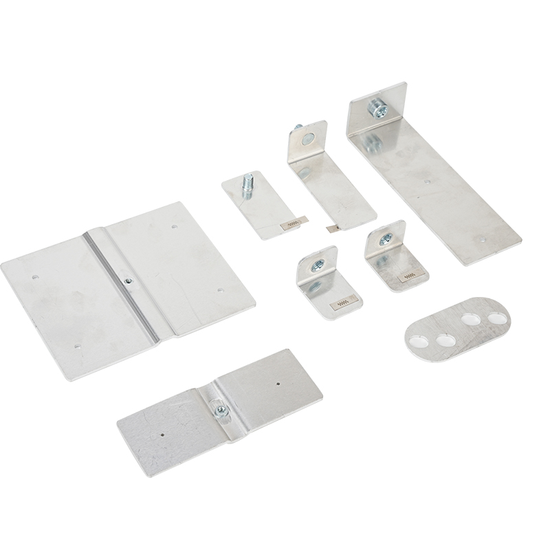
Copper Aluminum Connecting Plate for Power Batteries is an engineered conductive component designed to connect dissimilar copper and aluminum electrical paths within lithium ion battery modules, energy storage systems, battery PACKs, busbar assemblies, and related power electronics.
Copper and aluminum are both widely used in electrical conductors, but they offer different combinations of electrical conductivity, density, cost, mechanical properties, oxidation behavior, and joining characteristics. Lithium ion cells also commonly use different current collector materials at the positive and negative electrodes. In conventional lithium ion battery chemistry, aluminum foil is generally used for the positive electrode current collector while copper foil is generally used for the negative electrode current collector.
This material difference creates a practical interconnection challenge when a battery module needs to transition from a copper conductive path to an aluminum conductive path.
A Cu Al composite connection sheet addresses this requirement by combining copper and aluminum into a single composite component. Depending on its design, the copper region can be connected to a copper terminal, copper tab, nickel plated copper part, or another copper conductor, while the aluminum region can be connected to an aluminum terminal, aluminum busbar, aluminum housing, or aluminum battery component.
The key characteristic is the metallurgically bonded Cu Al interface.
Instead of simply placing copper and aluminum together with an adhesive layer, a suitable composite manufacturing process creates a permanent bonded interface between the two metals. Depending on the product design and manufacturing route, technologies can include roll bonding, diffusion bonding, explosive welding, friction based joining, or other controlled metallurgical processes.
This construction can provide a controlled transition between two dissimilar metals while reducing the need for a large direct Cu Al mechanical contact joint.
Cu Al composite conductors are particularly attractive where a battery system requires:
High electrical conductivity
Reduced conductor weight
Copper to aluminum transition
Controlled joining geometry
Reliable mechanical integrity
Compatibility with battery welding processes
Compact module architecture
Reduced use of heavy copper
Customized stamped or laser cut components
Aluminum copper busbars are already an important part of lithium ion battery interconnection technology, while research continues to address the challenges associated with joining dissimilar copper and aluminum materials.
2. Product Positioning
A Cu Al Composite Connection Sheet can be positioned as a conductive transition component, rather than simply as a conventional copper sheet or aluminum sheet.
Its purpose is to provide two material zones within one engineered component:
Copper conductive zone → metallurgical transition interface → aluminum conductive zone
This structure can be used where a battery architecture requires a transition between different conductor materials.
Typical applications include:
Power battery modules
Energy storage battery PACKs
Prismatic cell assemblies
Pouch cell interconnections
Cylindrical cell modules
Battery busbars
CCS busbar systems
High current transition components
Battery terminal assemblies
DC power distribution
BMS related conductive structures
Energy storage cabinet connections
The design can also be adapted to different geometric configurations.
For example, a simple side by side configuration may have copper on one side and aluminum on the other. A layered construction may place copper on one or both surfaces of an aluminum core. A localized copper insert may be embedded into an aluminum conductive body.
The appropriate configuration depends on the electrical path, welding method, current rating, mechanical constraints, and available assembly space.
3. Why Copper and Aluminum Are Both Used in Battery Systems
Copper has excellent electrical conductivity and is widely used where low electrical resistance and high current carrying capability are important.
Aluminum has a lower density than copper and can significantly reduce conductor weight.
For battery packs, weight reduction is important because busbars, terminals, connectors, and other conductive structures can represent a meaningful portion of the overall electrical interconnection mass.
A copper conductor and an aluminum conductor with equivalent electrical performance do not necessarily have the same mass. This makes aluminum attractive for larger conductive structures.
However, battery cells may already contain both copper and aluminum conductive components.
The challenge is therefore not simply choosing copper or aluminum.
The engineering challenge is creating a reliable transition between them.
4. What Is a Cu Al Composite Connection Sheet?
A Cu Al Composite Connection Sheet is a multilayer or side by side metallic composite in which copper and aluminum are joined through a controlled bonding interface.
Unlike an ordinary copper aluminum assembly made from two independent pieces, the composite is manufactured as one integrated component.
The basic construction can be represented as:
Copper Layer → Metallurgical Bond → Aluminum Layer
or:
Copper Zone → Metallurgical Transition → Aluminum Zone
The composite can then be cut, stamped, formed, drilled, bent, laser processed, or otherwise converted into the final battery connection component.
This provides a manufacturing advantage because the material supplier can deliver a pre-integrated Cu Al transition rather than requiring the battery manufacturer to create a Cu Al interface during final assembly.
5. Metallurgical Bonding Principle
Metallurgical bonding means that copper and aluminum are joined at the material interface through a controlled manufacturing process rather than being separated by an adhesive layer.
Possible technologies include:
Roll bonding
Explosive welding
Diffusion bonding
Friction welding
Friction based solid state joining
Specialized clad manufacturing processes
The exact process influences interface structure, bonding strength, electrical properties, residual stress, and manufacturability.
The goal is to create a stable interface while controlling the formation of undesirable intermetallic compounds.
This is important because copper and aluminum can form intermetallic phases when subjected to suitable temperature and diffusion conditions. In welded Cu Al battery busbars, intermetallic formation can influence mechanical and electrical properties. Research on Cu Al busbars has specifically identified the need to control interface phases and process heat input.
6. Roll Bonding
Roll bonding is one of the important technologies used to manufacture clad metallic sheets and strips.
In a typical roll bonding process, prepared copper and aluminum surfaces are brought together under controlled pressure and deformation.
The rolling operation can create intimate metallic contact and establish a bonded interface.
Advantages can include:
Continuous production
Large sheet widths
Controlled thickness
Good dimensional consistency
Adjustable layer ratios
Efficient material utilization
Compatibility with subsequent stamping
Roll bonding is particularly suitable when a large volume of composite strip material is required.
The resulting material can then be slit into narrower widths or converted into battery components.
7. Explosive Welding
Explosive welding is a solid state joining technology capable of bonding certain dissimilar metals.
The process uses controlled explosive energy to accelerate one metal plate against another.
The resulting high velocity collision can create a metallurgical interface.
For Cu Al composites, this method can produce strong bonding across dissimilar metals.
However, the suitability of explosive welding depends on the desired thickness, product geometry, production environment, and downstream processing requirements.
For thin battery connection materials, roll bonding or other continuous processes may be more practical depending on the design.
8. Diffusion Bonding
Diffusion bonding uses temperature, pressure, and time to create a metallurgical connection between prepared metal surfaces.
Atomic diffusion occurs across the interface.
The process can produce highly controlled joints when the materials and process parameters are properly selected.
However, diffusion bonding may require more controlled processing conditions than high-speed continuous roll bonding.
9. Side by Side Cu Al Composite Construction
A side by side configuration places copper and aluminum next to each other within the same conductive sheet.
A simplified structure is:
Copper Section | Cu Al Transition Interface | Aluminum Section
This configuration is particularly useful when one end of a connector must be welded or joined to copper while the opposite end must be connected to aluminum.
The transition zone can be positioned according to the component geometry.
This design can reduce the need for a separate Cu Al mechanical joint.
10. Single Sided Cladding
In a single sided clad structure, a copper layer is bonded to one surface of an aluminum base.
The structure can be represented as:
Copper / Aluminum
This configuration can be useful when the electrical connection requires copper on one surface while the remaining body benefits from aluminum's lower density.
It may also be useful for customized terminal structures.
11. Double Sided Cladding
A double sided structure can be configured as:
Copper / Aluminum / Copper
This sandwich construction can provide copper conductive surfaces on both sides.
The design may be useful for specialized busbar or terminal applications.
The copper layer thickness can be adjusted according to the current path and welding requirements.
12. Aluminum Base with Embedded Copper
Another structure uses an aluminum base with a localized copper strip.
This can create a conductive transition in which only the required welding region contains copper.
Such a design can reduce the amount of copper required compared with a fully copper conductor.
This approach can be especially useful where a high conductivity copper zone is required only around a terminal or welding area.
13. Copper Grades
Copper selection depends on conductivity, mechanical requirements, welding compatibility, and cost.
Common copper options can include:
T2
C1100
C10200
Other application-specific copper grades
T2 and C1100 are widely recognized industrial copper designations.
Oxygen-free copper such as C10200 can be selected for applications where its material characteristics are beneficial.
The actual copper grade should be specified using the applicable material standard rather than relying solely on commercial names.
14. Aluminum Grades
Common aluminum options can include:
1060
1070
1100
5052
High-purity aluminum grades can offer good electrical conductivity.
Alloyed grades such as 5052 can provide different mechanical characteristics.
Temper selection can also affect formability and strength.
The appropriate aluminum grade should therefore be selected according to the final component geometry and mechanical requirements.
15. Copper Layer Ratio
The copper layer ratio is an important design parameter.
A higher copper proportion can increase the conductive contribution of copper but also increases material cost and weight.
A lower copper proportion can reduce weight and material usage but may change the electrical and welding characteristics.
For example, a general-purpose composite may use a copper proportion in the range of approximately 10% to 20%, while higher-current applications may require a different design.
However, copper ratio should never be selected based only on a generic current multiplier.
Current carrying capability depends on:
Cross-sectional area
Copper and aluminum conductivity
Temperature
Cooling
Current waveform
Duty cycle
Contact resistance
Geometry
Welding resistance
Enclosure conditions
Therefore, actual current rating should be validated through electrical and thermal testing.
16. Thickness Range
Composite connection sheets can be manufactured in various thicknesses.
A broad industrial range may extend from approximately 0.07 mm to 15 mm depending on the manufacturing method and product structure.
For many battery auxiliary components, a thinner range such as approximately 0.15 mm to 3 mm can be more practical.
Thin materials can be suitable for:
Battery tabs
Small transition connectors
Stamped conductive pieces
Pouch cell connections
Thicker materials may be used for:
Busbars
Terminal blocks
High current transition components
Structural conductive parts
17. Width and Forming
Composite sheet and strip products can be supplied in different widths.
Possible forms include:
Narrow strips
Wide coils
Sheets
Stamped blanks
Die cut parts
Laser cut components
Depending on the material thickness and construction, processing can include:
Stamping
Punching
Laser cutting
Bending
Forming
Drilling
Slitting
The processing method should be selected to avoid damaging the bonded interface.
18. Electrical Conductivity
Electrical conductivity is one of the most important characteristics of a battery connection component.
The electrical resistance of a Cu Al composite is determined by more than the bulk resistivity of copper.
It depends on:
Copper cross-sectional area
Aluminum cross-sectional area
Current path length
Interface design
Contact resistance
Surface condition
Temperature
Geometry
Welding quality
A reference resistivity value of ≤ 0.0245 Ω·mm²/m may be used for a particular product specification, but it should not be treated as a universal performance value for every Cu Al composite.
The final electrical resistance should be measured on the actual product.
19. Interface Resistance
A major advantage of metallurgically bonded material is that the Cu Al transition is integrated into the material itself.
However, it would be technically inaccurate to describe every metallurgically bonded interface as having literally zero electrical resistance.
Every real conductive path has some resistance.
The correct engineering objective is to achieve a low and stable interface resistance that remains acceptable over the intended service life.
This distinction is important when preparing technical product information.
20. Galvanic Corrosion Considerations
Copper and aluminum are dissimilar metals.
When dissimilar metals are electrically connected and exposed to a suitable electrolyte, galvanic corrosion can occur.
The risk depends on:
Electrochemical potential
Electrolyte
Moisture
Temperature
Surface area ratio
Electrical connection
Exposure duration
Protective coatings
Joint geometry
In battery environments, electrolyte contamination and condensation can create challenging corrosion conditions.
A metallurgically bonded transition can reduce the need for an exposed mechanical Cu Al interface, but it does not automatically make the entire component immune to corrosion.
Surface protection and sealing may still be required.
21. Aluminum Oxide
Aluminum naturally forms an oxide layer.
This oxide layer is electrically insulating relative to metallic aluminum.
The oxide can complicate certain welding and electrical contact processes.
This is one reason why aluminum welding requires careful process control.
When a Cu Al composite is designed correctly, the copper region can be used for copper-to-copper joining and the aluminum region can be used for aluminum-to-aluminum joining.
This can simplify the final welding process compared with directly joining copper to aluminum.
22. Like Metal Welding Advantage
One of the most important practical benefits of Cu Al composite connection technology is the ability to transition between metals before the final welding operation.
For example:
Copper battery tab → copper side of composite → aluminum side of composite → aluminum busbar
This can avoid placing a dissimilar Cu Al weld at every connection point.
Copper-to-copper and aluminum-to-aluminum welding can generally be easier to control than direct copper-to-aluminum welding, although each still requires an appropriate welding process.
Research on battery tab-to-busbar joining confirms that Cu Al dissimilar welding presents challenges related to physical properties and intermetallic compound formation.
23. Laser Welding
Laser welding is widely investigated and used for battery tab and busbar interconnections.
Copper and aluminum have different optical absorption and thermal conductivity characteristics, which can complicate direct laser welding.
A Cu Al composite can allow the manufacturer to weld each metal to a compatible counterpart.
The copper region can be optimized for copper welding.
The aluminum region can be optimized for aluminum welding.
The exact laser parameters must be developed for the actual thickness, surface condition, laser wavelength, power, beam profile, welding speed, and joint design.
24. Ultrasonic Welding
Ultrasonic welding is another joining method used in battery manufacturing.
It can be suitable for certain thin conductive tabs and foils.
The welding process uses high-frequency mechanical vibration and pressure to establish a solid state bond.
Cu Al composite components can be designed so that the appropriate metal side is exposed for ultrasonic joining.
Process validation is necessary because excessive vibration or deformation may affect thin battery components.
25. Resistance Welding
Resistance welding uses electrical resistance to generate heat at a joint.
It can be suitable for certain battery tab and busbar applications.
The electrical and thermal properties of copper and aluminum influence welding behavior.
Composite materials require careful electrode placement and process development.
26. CMT and Related Welding Processes
Controlled metal transfer processes can be used for selected aluminum welding applications.
Where the aluminum side of a composite is connected to an aluminum component, the welding process can be optimized for aluminum rather than for a direct copper aluminum interface.
This can help simplify process development.
However, the final welding method must be selected according to component thickness and manufacturing requirements.
27. Prismatic Battery Applications
Prismatic cells often contain rigid metal housings and defined terminal structures.
Cu Al composite components can be used for:
Terminal transition pieces
Top cover connectors
Negative terminal transition structures
Busbar interfaces
High current conductive components
A composite terminal can allow the internal copper path to transition to an external aluminum structure.
28. Pouch Cell Applications
Pouch cells commonly use thin electrode tabs.
Copper is associated with the negative side and aluminum with the positive side in conventional lithium ion cell construction.
Composite conductive materials can be designed for tab transition applications.
However, pouch cell tabs require careful consideration of:
Tab thickness
Sealing area
Heat affected zone
Mechanical flexibility
Electrolyte compatibility
Welding method
Polymer sealing film
The composite should not interfere with the pouch sealing system.
29. Cylindrical Cell Modules
Cylindrical battery formats such as 18650 and 21700 are frequently connected in series and parallel configurations.
Traditional battery interconnection designs can use nickel, nickel plated steel, copper, aluminum, or combinations of these materials.
Cu Al composite materials can be used where the module architecture requires a copper to aluminum transition.
Possible applications include:
Series busbars
Parallel busbars
Terminal transition pieces
High current conductive links
Module-level connectors
The actual material selection depends on current, welding process, and module architecture.
30. Energy Storage Battery Systems
Energy storage systems often operate at significant continuous current.
They may contain:
Battery racks
Battery modules
DC busbars
Contactors
Fuses
Disconnects
Power distribution components
BMS systems
Weight, electrical resistance, thermal management, and assembly reliability are important.
Cu Al composite components can provide a transition between copper and aluminum components within these systems.
31. Energy Storage Cabinet Applications
In energy storage cabinets, conductive paths may extend from individual modules to larger DC distribution structures.
A composite transition component can be used where:
Copper terminal → Cu Al transition → aluminum busbar
or the reverse configuration is required.
This can provide a controlled transition while maintaining a compact structure.
32. CCS Integrated Busbar Systems
Cell Contact Systems, often abbreviated as CCS, integrate electrical connections and sensing components.
A CCS structure can contain:
Busbars
FPC
Sampling circuits
Insulation components
Protective films
Connectors
Cu Al composite conductive parts can be considered where a localized material transition is required.
The composite can be integrated into a molded or laminated busbar structure depending on the system design.
33. BMS Sampling Applications
Battery Management Systems monitor:
Cell voltage
Temperature
Current
Pack status
Fault conditions
High current paths and low current sensing paths must be carefully separated.
Composite conductive components can be designed to support high current paths while maintaining an appropriate arrangement for signal acquisition.
The electrical isolation between power conductors and signal circuits must be maintained.
34. CTM, CTP and CTC Battery Architectures
Battery pack architecture continues to evolve.
Traditional Cell to Module designs place multiple cells inside a module.
Cell to Pack designs reduce intermediate structures.
Cell to Chassis concepts integrate battery structures more deeply into the vehicle.
As module integration increases, conductive components must become:
More compact
Lighter
More integrated
More precisely formed
Easier to automate
Cu Al composite components can support these objectives when appropriately designed.
35. Weight Reduction
Copper is denser than aluminum.
Using aluminum for larger conductor sections while retaining copper only where its conductivity or welding characteristics are needed can reduce component mass.
This is one of the main reasons composite conductors are attractive for transportation and battery applications.
The exact weight reduction depends on:
Copper ratio
Aluminum thickness
Geometry
Current requirement
Cross-sectional area
The statement that a composite conductor is always one third or one half the weight of copper should therefore not be treated as universal.
36. Mechanical Strength
A Cu Al composite must withstand mechanical forces generated during:
Assembly
Welding
Vibration
Transportation
Thermal cycling
Service
A reference tensile strength range such as 90 to 170 MPa may be used for a particular product design, but the actual value depends on the material grades and manufacturing process.
Mechanical testing should include both the composite body and the bonded interface.
37. Peel Strength of Clad Interface
Peel strength can be used to characterize the bonding integrity of layered composite structures.
A reference value such as ≥12 N/mm may be specified for certain product constructions.
However, the test method, specimen geometry, thickness, interface design, and standard must be identified.
A numerical value without a test method is incomplete technical information.
38. Thermal Cycling
Battery modules may experience repeated heating and cooling.
Copper and aluminum have different coefficients of thermal expansion.
During thermal cycling, this difference can create stress at the interface.
A properly engineered metallurgical bond must maintain integrity during repeated thermal expansion and contraction.
Thermal cycling validation can therefore include:
Interface inspection
Electrical resistance measurement
Tensile or peel testing
Visual examination
Cross-sectional analysis
39. Vibration Resistance
Electric vehicles and energy storage systems can experience mechanical vibration.
Battery busbars must resist fatigue.
A research study on Cu Al busbars for battery packs highlights vibration and fatigue as relevant considerations for busbar reliability.
The final component design should therefore consider:
Free length
Bend radius
Mounting points
Joint geometry
Component mass
Vibration amplitude
Frequency
40. Shock Resistance
Battery modules may experience transportation shock, vehicle impacts, or mechanical handling loads.
The Cu Al composite component should be designed to avoid excessive stress concentration.
Rounded corners and appropriate bend radii can improve mechanical durability.
41. Surface Treatments
Cu Al composite components can be supplied with different surface treatments.
Possible options include:
Bare copper
Bare aluminum
Nickel plated surface
Tin plated surface
Protective coating
Insulating coating
Surface treatment should be selected according to:
Welding method
Contact resistance
Corrosion environment
Storage conditions
Electrical requirements
42. Nickel Plating
Nickel plating can be used on selected conductive surfaces.
It may improve surface durability and corrosion resistance in appropriate environments.
However, plating also changes welding behavior.
Therefore, the welding process must be validated with the actual plated surface.
43. Tin Plating
Tin plating can provide a conductive surface suitable for certain electrical contacts.
It can also improve solderability in selected applications.
Again, plating thickness and surface condition should be controlled.
44. Insulating Coatings
Some composite conductive parts may require partial insulation.
An insulating coating can be applied to selected areas while leaving the welding or electrical contact regions exposed.
This approach can simplify battery module assembly.
However, the coating must be compatible with:
Operating temperature
Electrical requirements
Chemical exposure
Mechanical abrasion
Welding process
45. Stamping
Stamping is suitable for high-volume production of repetitive shapes.
The composite sheet can be converted into:
Tabs
Connectors
Busbars
Terminal plates
Transition pieces
Tooling should account for differences in copper and aluminum mechanical properties.
Improper stamping conditions can cause deformation or stress concentration near the bonded interface.
46. Laser Cutting
Laser cutting provides flexible geometry and is suitable for prototypes or lower-volume production.
It can create:
Holes
Slots
Complex outlines
Narrow conductive paths
Customized terminals
The laser process should be controlled to minimize undesirable heat effects at the composite interface.
47. Bending and Forming
Battery connection plates may need three-dimensional geometry.
Bending design should consider:
Material thickness
Copper ratio
Interface orientation
Bend radius
Temper
Work hardening
The composite interface should not be placed in an unnecessarily severe deformation zone.
48. Design of Transition Zones
The transition interface is a critical region.
An abrupt geometry change can produce local stress concentration.
A well-designed transition can provide smoother mechanical and electrical distribution.
Design considerations include:
Interface width
Copper thickness
Aluminum thickness
Transition length
Bend location
Welding location
Current density
49. Current Density
Current density is an important factor in busbar design.
High current concentrated into a small cross section increases resistive heating.
A simplified relationship is:
Electrical resistance increases as conductor length increases and decreases as cross-sectional area increases.
For a composite conductor, the current distribution between copper and aluminum depends on their electrical properties and geometry.
Thermal modeling and prototype testing can therefore be important for high-current battery systems.
50. Joule Heating
When current flows through a conductor, electrical resistance produces heat.
The heat generation is related to current and resistance.
Therefore, reducing resistance can improve thermal performance.
A composite transition should be evaluated as a complete current path rather than judging the copper and aluminum sections separately.
The welds and terminal contacts may contribute more resistance than the bulk composite material.
51. Contact Resistance
Contact resistance can arise at:
Battery terminals
Welding interfaces
Bolted joints
Plated surfaces
Mechanical connectors
A composite connection sheet does not automatically eliminate contact resistance at its external connections.
The objective is to minimize and stabilize resistance throughout the complete conductive path.
52. Why Mechanical Cu Al Joints Can Be Challenging
A mechanical joint between copper and aluminum can be exposed to:
Moisture
Oxygen
Contaminants
Thermal cycling
Vibration
Mechanical joints also depend on sustained contact pressure.
Changes in surface condition or joint pressure can influence contact resistance.
Research on Cu Al battery busbars notes that mechanical fastening can expose dissimilar-metal interfaces to environmental effects and can present long-term reliability concerns.
53. Avoiding Overstated Corrosion Claims
It is not technically correct to claim that a Cu Al composite makes galvanic corrosion impossible.
The composite reduces the need for certain exposed Cu Al mechanical contact interfaces, but the component can still experience corrosion at:
Exposed aluminum
Exposed copper
Welded regions
Plated regions
Fastener interfaces
Damaged coatings
Environmental sealing and appropriate surface protection remain important.
54. Battery Electrolyte Environment
Battery electrolyte contamination can be particularly aggressive toward metallic materials.
However, the actual environment varies considerably depending on cell construction and failure mode.
A busbar should not be assumed to be directly exposed to electrolyte during normal operation.
The correct design objective is to prevent electrolyte leakage or contamination from reaching vulnerable conductive interfaces.
55. Continuous Current Applications
For continuous discharge systems, conductor temperature is an important consideration.
A composite component should be evaluated under the intended:
Current
Duty cycle
Ambient temperature
Cooling conditions
Mounting configuration
A generic statement such as “15% copper is sufficient for 1C to 3C” cannot be universally applied because C-rate alone does not determine current.
For procurement, the actual current in amperes and the thermal environment should be specified.
56. High Rate Power Battery Applications
High power battery systems can require very high instantaneous current.
In these systems, the copper region may need to be increased or locally thickened.
Potential design strategies include:
Increased copper ratio
Local copper inserts
Wider conductor sections
Parallel conductors
Improved cooling
Reduced joint resistance
The final selection should be based on thermal-electrical testing.
57. Energy Storage Applications
Energy storage systems often emphasize long operating life.
Important considerations include:
Continuous current
Thermal stability
Corrosion resistance
Mechanical fatigue
Maintenance requirements
Connection reliability
A Cu Al composite can provide a useful material transition where system architecture already uses both copper and aluminum.
58. Product Selection Guidelines
When selecting a Cu Al composite connection plate, consider:
Determine:
Continuous current
Peak current
Voltage
Duty cycle
Acceptable resistance
Heat generation
Determine:
Tensile load
Vibration
Shock
Bending
Assembly stress
Determine:
Temperature
Humidity
Chemical exposure
Corrosion conditions
Determine:
Welding technology
Stamping
Laser cutting
Bending
Automated assembly
59. Common Procurement Mistakes
One common mistake is selecting a composite solely according to thickness.
Thickness alone does not determine current carrying capability.
Another mistake is selecting the copper ratio without considering the complete current path.
A third mistake is choosing a material based on nominal conductivity without testing the actual welded assembly.
Other common errors include:
Ignoring surface treatment
Ignoring welding orientation
Ignoring thermal expansion
Ignoring interface testing
Ignoring vibration
Assuming all aluminum grades behave the same
Assuming all copper grades have identical welding performance
60. Welding Orientation
A key assembly principle is to connect each side of the composite to a compatible metal whenever possible.
For example:
Copper tab → Copper side
and:
Aluminum tab → Aluminum side
This can reduce the need for direct Cu Al welding.
However, the actual orientation must follow the battery architecture and welding process.
61. Interface Inspection
Quality inspection can include:
Visual inspection
Dimensional inspection
Electrical resistance testing
Tensile testing
Peel testing
Cross-sectional metallography
Ultrasonic inspection
Microscopic interface analysis
The appropriate method depends on the product thickness and manufacturing process.
62. Cross Section Analysis
Cross-sectional examination can reveal:
Delamination
Voids
Cracks
Intermetallic layers
Interface uniformity
Thickness ratio
For critical battery applications, interface characterization can provide valuable process control information.
63. Electrical Resistance Testing
Four-wire resistance measurement can be used to characterize low-resistance conductive components.
This can provide more reliable results than simple two-wire measurements when resistance values are very low.
Testing should be performed on production-representative samples.
64. Thermal Testing
Thermal testing can evaluate temperature rise under current.
A useful test can include:
Mount the component in the intended configuration.
Apply the specified current.
Monitor surface and joint temperature.
Record temperature rise.
Continue for the required duration.
Inspect the component after testing.
Thermal imaging can help identify localized high-resistance areas.
65. Long-Term Reliability
Long-term reliability requires more than initial mechanical strength.
A reliable battery connector should maintain acceptable:
Electrical resistance
Mechanical integrity
Interface bonding
Surface condition
Welding performance
after environmental exposure.
66. Thermal Aging
Thermal aging can reveal changes in:
Bond strength
Surface oxidation
Coating condition
Electrical resistance
Mechanical properties
Testing temperatures should reflect realistic service conditions rather than arbitrary extreme values.
67. Humidity Aging
Humidity testing can evaluate corrosion and environmental stability.
It can be particularly useful for energy storage equipment installed in humid environments.
After humidity exposure, samples can be checked for:
Corrosion
Delamination
Resistance increase
Surface discoloration
Mechanical degradation
68. Salt Spray Testing
Salt spray testing may be appropriate for selected transportation or outdoor equipment.
However, salt spray results should not automatically be interpreted as equivalent to battery electrolyte resistance.
Each test represents a different environmental condition.
69. RoHS and REACH
Environmental compliance can be part of the procurement specification.
RoHS addresses restrictions on certain hazardous substances in electrical and electronic equipment.
REACH addresses chemical substances and their registration, evaluation, authorization, and restriction within the European regulatory framework.
Compliance documentation should be obtained for the actual material and surface treatment.
70. GB/T 32468
The supplied product information references GB/T 32468-2015 Copper clad aluminum plate, sheets and strips.
This standard has now been superseded.
The current Chinese national standard is GB/T 32468-2025, Copper clad aluminum plates, sheets, strips and foils, which was published on March 28, 2025 and took effect on October 1, 2025.
Therefore, current product documentation should reference GB/T 32468-2025 where applicable rather than presenting GB/T 32468-2015 as the current standard.
71. General Technical Data Reference
The following table can be used as a general product-page reference. Actual values should be confirmed against the final product specification.
| Item | Typical Reference |
|---|---|
| Product Type | Cu Al Composite Connection Sheet |
| Main Function | Copper to aluminum conductive transition |
| Copper Options | T2, C1100, C10200 or application-specific grades |
| Aluminum Options | 1060, 1070, 1100, 5052 or application-specific grades |
| Cladding Method | Roll bonding, diffusion bonding, explosive welding or other metallurgical bonding |
| Overall Thickness | Approximately 0.07 to 15 mm depending on construction |
| Common Battery Component Range | Approximately 0.15 to 3.0 mm |
| Copper Layer Ratio | Application-specific, commonly around 10% to 20% |
| Width | Narrow strip to wide sheet depending on production method |
| Forming | Stamping, punching, bending, laser cutting and customized forming |
| Surface Treatment | Bare, nickel plated, tin plated or coated |
| Reference Peel Strength | ≥12 N/mm for a specified construction and test method |
| Reference Tensile Strength | Approximately 90 to 170 MPa for selected constructions |
| Reference Elongation | Approximately 5% to 35% |
| Reference Resistivity | ≤0.0245 Ω·mm²/m for a specified material construction |
| Temperature Range | Application specific; validation required |
| Compliance | Applicable RoHS, REACH and current material standards |
| Current Chinese Standard | GB/T 32468-2025 where applicable |
72. Difference Between Cu Al Composite Sheet and Separate Metal Plates
A conventional approach may use:
Copper plate + mechanical connector + aluminum plate
A composite approach uses:
Copper section + metallurgical interface + aluminum section
The composite approach integrates the transition into the material itself.
Potential benefits include:
Compact structure
Reduced component count
Controlled transition zone
Simplified downstream assembly
Reduced exposed Cu Al contact area
Better compatibility with automated processing
73. Difference Between Cu Al Composite and Copper Busbar
A pure copper busbar offers excellent conductivity but has higher density.
A Cu Al composite can reduce the amount of copper used while retaining copper where it is most beneficial.
This can provide a compromise between:
Electrical performance + weight + material cost + welding compatibility
The exact benefit depends on the design.
74. Difference Between Cu Al Composite and Aluminum Busbar
An aluminum busbar is lightweight and can provide good conductivity relative to its mass.
However, certain battery terminals and welding zones may require copper.
A Cu Al composite can place copper selectively where required while using aluminum elsewhere.
75. Difference Between Cu Al Composite and Direct Cu Al Welding
Direct Cu Al welding creates a dissimilar metal joint at the welding interface.
Such joints require careful process control because copper and aluminum have different thermal and physical properties, and intermetallic compounds may form.
Studies of battery Cu Al joints have reported challenges involving intermetallic phases, electrical resistance, joint temperature, and mechanical strength.
A composite transition can move the dissimilar-metal interface away from the final battery tab-to-busbar welding point.
76. Design for Battery Pack Automation
Modern battery manufacturing increasingly uses automated assembly.
Composite connection sheets can be supplied as:
Coils
Strips
Stamped parts
Die cut parts
Laser cut parts
Preformed terminals
This supports automated feeding and placement.
Dimensional consistency becomes particularly important.
77. Packaging and Handling
Copper aluminum composite material should be protected from:
Moisture
Dirt
Scratches
Surface contamination
Mechanical deformation
Battery welding surfaces should remain clean.
Packaging should prevent the material from being bent or compressed beyond its intended geometry.
78. Storage
Recommended storage conditions depend on surface treatment and product design.
General principles include:
Keep material dry
Avoid condensation
Protect from contamination
Keep original packaging intact
Avoid corrosive atmospheres
Prevent mechanical damage
Use material within its specified shelf-life requirements where applicable
79. Customized Battery Connection Components
Cu Al composite material can be converted into customized parts.
Examples include:
Battery terminal plates
Transition busbars
Conductive strips
Cell interconnects
Stamped tabs
Power connectors
Energy storage transition bars
Customization can include:
Thickness
Width
Copper ratio
Length
Hole pattern
Bend geometry
Surface treatment
Insulation area
80. Engineering Collaboration
For high-volume battery projects, material suppliers and component designers may need to coordinate on:
Current requirements
Cell chemistry
Cell format
Welding process
Mechanical design
Cooling system
Environmental conditions
Inspection criteria
This collaborative approach can prevent material selection errors.
81. Application Example: Prismatic Battery Module
A prismatic module may contain aluminum housing components and copper internal conductive paths.
A Cu Al composite terminal can provide:
Copper internal connection → composite transition → aluminum external connection
The copper side can be designed for a copper welding process.
The aluminum side can be designed for aluminum welding.
This arrangement can simplify the terminal transition.
82. Application Example: Pouch Battery
A pouch cell can use copper on the negative tab and aluminum on the positive tab.
A composite transition component can be used where the module architecture requires a change from one conductive material to another.
The design must preserve pouch sealing and prevent mechanical stress on the cell.
83. Application Example: Cylindrical Battery Pack
In a cylindrical cell module, individual cells can be interconnected through busbars.
A composite component can provide a transition between copper and aluminum sections.
The final design can be stamped or laser cut to match the cell layout.
84. Application Example: Energy Storage Busbar
An energy storage system may use aluminum busbars to reduce weight while certain terminal components use copper.
A Cu Al transition plate can connect these two conductive structures.
This avoids making every downstream connection a direct Cu Al joint.
85. Application Example: CCS System
A composite conductive component can be integrated into a CCS assembly.
The copper region can serve a high conductivity connection point, while the aluminum section can connect to a larger aluminum conductive structure.
The component can be combined with:
FPC
Insulation film
Molded plastic
Protective cover
86. Reliability Strategy
A reliable composite connection system should be evaluated across three levels:
Evaluate:
Composition
Interface
Thickness
Conductivity
Evaluate:
Geometry
Welding
Bending
Resistance
Mechanical strength
Evaluate:
Current
Temperature
Vibration
Aging
Environmental exposure
This layered qualification approach provides better reliability than evaluating the raw material alone.
87. Common Questions
It is a conductive material combining copper and aluminum through a metallurgical bonding process for electrical transition applications.
Copper provides high electrical conductivity and favorable joining characteristics in certain applications, while aluminum offers lower density and potential weight savings.
It can be suitable for selected battery terminals, tabs, busbars, and transition components when the material and welding process are properly qualified.
No. The selection depends on current, geometry, thermal requirements, welding, mechanical design, and cost.
No. It can reduce certain exposed Cu Al mechanical interfaces, but corrosion protection remains necessary where the composite is exposed to moisture or corrosive environments.
Yes, depending on the construction. The copper side can be designed for copper-compatible joining and the aluminum side for aluminum-compatible joining.
88. Frequently Asked Technical Questions
A true Cu Al clad connection sheet is generally based on metallurgical bonding rather than a conventional organic adhesive layer.
Yes. The copper-to-aluminum ratio can be designed according to electrical, mechanical, welding, and weight requirements.
Many sheet and strip constructions can be stamped, provided the material thickness, interface structure, and forming requirements are compatible.
Suitable composite constructions can be laser cut, but process parameters should be developed to protect the interface and maintain dimensional accuracy.
Selected surfaces can be nickel plated, tin plated, or otherwise treated according to the application.
89. Why Cu Al Composite Materials Matter for New Energy
The development of electric vehicles and energy storage systems is increasing demand for lightweight conductive structures.
Battery packs must simultaneously meet requirements for:
High current
Low resistance
Low mass
High reliability
Compact packaging
Automated assembly
Thermal management
Copper aluminum composite technology provides a way to combine the advantages of two conductive metals within one component.
It does not eliminate the engineering challenges of battery interconnection, but it can provide another design option for optimizing the conductive path.
90. Future Development Trends
Future Cu Al composite connection components are likely to move toward:
Thinner and lighter designs
Higher current density
Localized copper reinforcement
Improved welding surfaces
Integrated insulation
More precise stamping
Automated feeding
CCS integration
Customized terminal geometries
Improved corrosion protection
Higher dimensional consistency
Battery architectures are also moving toward greater structural integration.
This creates demand for conductive components that combine electrical, mechanical, thermal, and manufacturing functions in increasingly compact forms.
91. Conclusion
Copper Aluminum Connecting Plate for Power Batteries is a specialized conductive transition component that combines copper and aluminum through a controlled metallurgical interface.
Its major purpose is to provide a reliable transition between copper and aluminum conductive paths while supporting the weight, electrical, mechanical, welding, and manufacturing requirements of modern battery systems.
The product can be configured as:
Single sided copper clad aluminum
Double sided copper aluminum copper
Side by side copper aluminum
Aluminum base with embedded copper
Customized terminal structures
Composite busbars
Battery tabs
Conductive strips
Potential applications include prismatic batteries, pouch cells, cylindrical cell modules, energy storage cabinets, battery PACKs, CCS assemblies, BMS power paths, and other new energy electrical systems.
The most important technical principle is that the composite should be evaluated as a complete conductive and mechanical system rather than judged by copper or aluminum properties alone.
Electrical resistance, interface integrity, welding performance, thermal behavior, mechanical strength, corrosion resistance, and long-term reliability should all be validated under the intended application conditions.
For current Chinese standard references, product documentation should take account of GB/T 32468-2025, which replaced GB/T 32468-2015 as the current standard for copper clad aluminum plates, sheets, strips and foils.
With appropriate material selection, interface engineering, surface treatment, welding design, and quality control, Cu Al composite connection sheets can provide a practical conductive transition solution for lightweight lithium ion battery modules and energy storage systems.
This website uses cookies to ensure you get the best experience on our website.


 Phone
Phone