

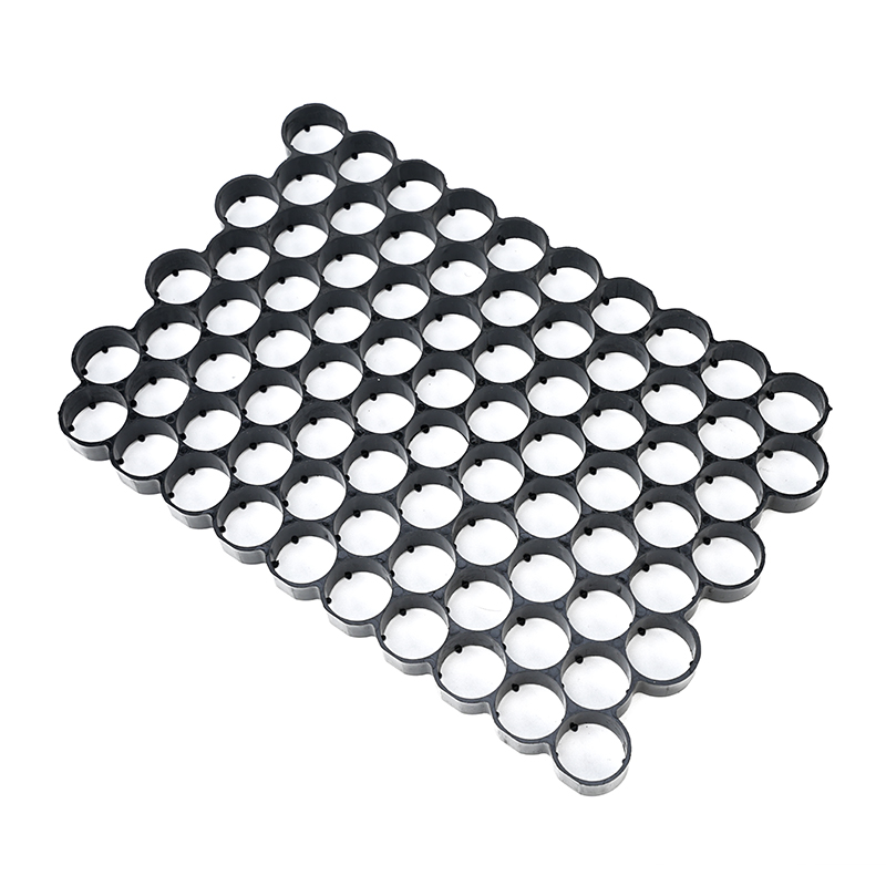
The 40135 8x10 Staggered Battery Cell Mounting Bracket is a specialized plastic cell positioning component designed for cylindrical battery packs using an offset or staggered cell arrangement. Unlike conventional straight-row battery holders, a staggered mounting structure positions adjacent cylindrical cells with an intentional offset. This configuration can improve space utilization, create a compact honeycomb-style arrangement, and provide a practical mechanical framework for multi-cell battery pack assembly.
The 40135 8x10 configuration is intended for applications where a large number of cylindrical cells need to be organized inside a limited enclosure volume. The staggered geometry can be particularly useful when battery designers want to optimize internal packaging while maintaining controlled cell positioning.
A battery mounting bracket is more than a simple plastic spacer. It can influence cell alignment, assembly efficiency, ventilation, cable routing, insulation planning, nickel-strap installation, enclosure integration, and overall module organization. For this reason, the geometry and material of a battery Cell Mounting Bracket should be selected according to the actual cell dimensions and working environment.
The 40135 8x10 Staggered Battery Cell Mounting Bracket can be manufactured in several engineering plastic options, including ABS, PC, PP, and PA66. Material selection depends on temperature requirements, mechanical loading, flame-retardant requirements, cost targets, and the intended battery application.
For automotive-grade and export-oriented battery projects, UL94 V-0 flame-retardant material may be specified where required by the product design and applicable compliance requirements. ABS is commonly used for general-purpose battery holder applications, while PC can provide improved temperature resistance and PA66 can be considered for higher-temperature zones. PP can offer a cost-effective option for applications where the mechanical and thermal requirements are moderate.
The structure can also incorporate ventilation slots, cable routing slots, and nickel-strap cutouts when these features are included in the approved design. Such integrated features can help simplify battery assembly and reduce the need for additional positioning components.
Understanding Staggered Battery Cell Arrangement
A staggered battery cell arrangement places neighboring cylindrical cells at offset positions instead of aligning every cell directly in a straight grid.
This creates a pattern that resembles a honeycomb or close-packed structure.
For cylindrical cells, staggered positioning can offer several packaging advantages.
The circular shape of a cylindrical cell naturally creates unused spaces when cells are arranged in simple square grids. By shifting alternate rows, designers can make more efficient use of some of these spaces.
The result can be:
More compact cell positioning
Better use of internal enclosure space
Reduced unnecessary gaps
A visually organized honeycomb-style structure
Flexible module geometry
Efficient multi-cell packaging
The actual space-saving benefit depends on cell diameter, holder geometry, insulation requirements, thermal design, and enclosure dimensions. A staggered layout should therefore be evaluated as part of the complete battery pack rather than considered solely from a holder perspective.
What Does 8x10 Mean?
The 8x10 designation generally refers to a physical cell-position arrangement consisting of eight positions in one direction and ten positions in another.
The exact number of usable cell positions should always be confirmed from the engineering drawing because product naming conventions can vary.
The 8x10 physical arrangement should also be distinguished from the electrical configuration.
For example, a physical holder may organize a specific number of cells, while the battery may be electrically configured into a different series-parallel architecture.
Therefore, a complete battery specification should separately identify:
Cell model
Physical cell count
Physical holder layout
Series connection
Parallel connection
Nominal voltage
Battery capacity
BMS configuration
This distinction is important when designing or sourcing a customized battery holder.
40135 Cylindrical Cell Compatibility
The 40135 battery cell format is generally associated with a cylindrical cell size category. However, actual cell dimensions can vary according to manufacturer, cell construction, protective wrapping, terminal design, and dimensional tolerance.
For this reason, the actual cell drawing should be used when designing the holder.
Important dimensions may include:
Cell diameter
Cell length
Positive terminal geometry
Negative terminal geometry
Cell surface protection
Terminal height
Dimensional tolerance
A mounting bracket should be designed around the actual dimensions rather than relying only on the nominal cell model.
This is particularly important when a holder is intended for high-volume battery pack production.
Honeycomb-Style Battery Holder Design
One of the defining characteristics of a staggered battery cell mounting bracket is its honeycomb-style positioning.
A honeycomb arrangement can provide an efficient pattern for cylindrical objects.
In a battery module, the pattern can help:
Reduce unused internal space
Create a compact cell arrangement
Maintain consistent cell centers
Provide repeatable assembly positions
Support modular pack construction
The honeycomb-style structure can also make the battery pack visually and mechanically organized.
However, the final cell spacing must account for thermal requirements, electrical insulation, cell manufacturing tolerances, mechanical movement, and applicable design requirements.
Space optimization should never be performed without considering thermal management and electrical safety.
Space-Saving Battery Pack Architecture
Battery pack designers often face a fundamental challenge: maximizing energy capacity while keeping the package compact.
The holder occupies some internal space, but it also enables a more organized cell layout.
A well-designed staggered bracket can help balance these competing requirements.
Potential advantages include:
Compact cell arrangement
Better enclosure utilization
Reduced unnecessary structural space
Repeatable cell positioning
Easier module assembly
For electric mobility and portable energy systems, packaging efficiency can be particularly valuable because available enclosure volume is often limited.
Materials for 40135 Battery Mounting Brackets
Several plastic materials can be considered for battery cell mounting brackets.
The most appropriate material depends on the application.
Common options include:
ABS: Widely used for general battery holder applications.
PC: Suitable when greater temperature resistance and impact performance are required.
PP: A cost-effective thermoplastic option for applications with moderate mechanical and thermal requirements.
PA66: Suitable for demanding mechanical or high-temperature environments when the selected grade meets the application requirements.
Each material has advantages and limitations.
ABS Battery Cell Mounting Bracket
ABS is one of the most commonly used materials for molded battery holders.
It offers a practical balance of:
Processability
Mechanical strength
Surface appearance
Dimensional stability
Cost
Availability
For battery applications requiring improved flame performance, a flame-retardant ABS formulation can be selected.
A UL94 V-0 ABS grade may be specified for applications where that classification is required.
The exact temperature capability depends on the material grade, component geometry, load, and operating conditions.
For the stated 40135 holder application, an ABS version may typically be considered for environments around the 80–100°C range, subject to confirmation from the actual resin manufacturer's technical data.
PC Battery Cell Mounting Bracket
Polycarbonate is an engineering thermoplastic known for its strong impact resistance and useful heat resistance.
A PC battery holder may be considered when the application has:
Higher operating temperatures
Greater mechanical impact
More demanding structural requirements
Increased dimensional stability requirements
A PC version may typically be considered around the 120°C range, depending on the specific grade and operating conditions.
The actual continuous-use temperature should always be verified from the material data sheet.
PP Battery Cell Mounting Bracket
Polypropylene can provide a cost-effective solution for applications where high-temperature performance and high structural rigidity are not primary requirements.
Potential benefits include:
Low material cost
Low density
Good chemical resistance
Good molding characteristics
Lightweight construction
However, PP is generally softer and less rigid than many engineering plastics.
For this reason, PP may be appropriate for selected battery holder designs but should not automatically be substituted for ABS, PC, or PA66 in mechanically demanding applications.
PA66 Battery Cell Mounting Bracket
PA66 is a high-performance engineering thermoplastic that can provide strong mechanical properties and higher-temperature capability.
It may be considered for:
High-temperature battery zones
Structural components
High mechanical load areas
Industrial battery systems
Applications requiring improved rigidity
Certain PA66 grades can operate at temperatures above 150°C, but this figure should not be treated as a universal rating for all PA66 materials.
Actual performance depends on:
Resin grade
Reinforcement
Moisture content
Mechanical load
Exposure time
Temperature
Component geometry
Material Selection by Application
Material selection should be based on actual operating conditions.
For general battery PACK assemblies, flame-retardant ABS can provide a balanced solution.
For applications requiring higher temperature resistance, PC can be considered.
For cost-sensitive structures with moderate requirements, PP may be suitable.
For high-temperature zones, PA66 can be considered where its specific grade provides the required performance.
A simplified material-selection concept is:
General battery holder → ABS
Flame-retardant battery holder → Flame-retardant ABS
Higher-temperature application → PC
Cost-sensitive application → PP
High-temperature structural zone → PA66
The actual material decision should always be confirmed through engineering evaluation.
Temperature Resistance
Temperature resistance is an important specification for battery cell mounting brackets.
The expected temperature range can be affected by:
Cell current
Cell chemistry
Ambient temperature
Charging conditions
Discharging conditions
Thermal management
Enclosure design
Proximity to power electronics
Typical material guidance for this product concept can be expressed as:
ABS version: approximately 80–100°C
PC version: approximately 120°C
PA66 version: approximately 150°C or higher for suitable grades
These figures are general design references rather than guaranteed operating limits.
The final product temperature rating should be based on the actual polymer grade and manufacturer's technical documentation.
Why Temperature Resistance Matters
A battery holder may be exposed to heat generated by nearby cells or electrical components.
If the polymer softens excessively, dimensional accuracy may decrease.
Potential consequences include:
Cell position changes
Reduced mechanical retention
Holder deformation
Interference with electrical components
Reduced enclosure compatibility
Selecting a material with adequate thermal margin can therefore improve mechanical reliability.
UL94 V-0 Flame-Retardant Option
For automotive-grade and export-oriented battery projects, UL94 V-0 can be specified where required.
The purpose of specifying a recognized flame classification is to establish a clear material requirement.
Instead of simply requesting:
"Flame-retardant plastic"
a technical specification can state:
"Flame-retardant ABS, UL94 V-0 grade."
This provides a much clearer basis for material selection and documentation.
However, the exact UL94 classification should be verified against the specific material grade and applicable test conditions.
Automotive Battery Applications
Automotive battery packs require careful attention to mechanical stability, temperature, vibration, electrical insulation, and material performance.
A staggered battery holder can be useful where cylindrical cells must be packed efficiently within a vehicle battery enclosure.
Potential applications include:
Electric vehicle battery modules
Auxiliary battery systems
Automotive power systems
Electric mobility platforms
Specialized vehicle battery assemblies
Automotive applications often involve strict material and safety requirements. Therefore, the holder should be evaluated as part of the complete battery system.
Export-Oriented Battery Projects
Battery products intended for international markets may need to satisfy specific material, environmental, electrical, and product safety requirements.
A UL94 V-0 material option can be useful when the target product specification calls for a recognized flame-retardant material classification.
Additional compliance requirements may depend on:
Destination market
Battery chemistry
End-use application
Voltage
Product category
Transportation requirements
Customer specifications
RoHS compliance may also be relevant for materials and components supplied to markets where applicable.
RoHS Compliance
The stated 40135 8x10 Staggered Battery Cell Mounting Bracket can be specified as RoHS compliant where the selected material and manufacturing process meet the applicable requirements.
RoHS relates to restrictions on certain hazardous substances in electrical and electronic products.
For professional procurement, compliance should be supported by appropriate supplier documentation or testing records.
A general product statement should not replace project-specific compliance verification.
Ventilation Slots
Ventilation slots can be incorporated into the holder design when required.
Their purpose can include:
Supporting airflow
Reducing enclosed stagnant areas
Providing additional structural openings
Facilitating cable passage
Reducing unnecessary plastic material
In air-cooled battery systems, ventilation geometry can be an important part of thermal planning.
However, openings must be designed carefully to avoid weakening the holder or creating undesirable electrical exposure.
Cable Routing Slots
Battery packs contain multiple types of wires and cables.
These may include:
BMS wires
Temperature sensor wires
Balance wires
Power cables
Communication cables
Cable routing slots can help organize these wires within the battery module.
Integrated routing can provide:
Cleaner assembly
Reduced wire interference
Improved serviceability
More consistent cable positioning
Reduced assembly time
The dimensions of cable slots should match the actual wire size and routing requirements.
Nickel-Strap Cutouts
Nickel Strips are commonly used for electrical interconnection in certain cylindrical battery pack assembly methods.
A customized holder can potentially include nickel-strap cutouts.
These openings may provide space for:
Nickel strip positioning
Welding access
Interconnection routing
Strip alignment
The exact cutout shape depends on the battery electrical architecture and welding method.
Nickel-strap geometry should always be developed together with the electrical connection design.
Cell Welding and Holder Geometry
Battery cell welding may involve nickel strips or other conductive interconnection components.
A mounting bracket can influence access to the welding area.
When designing the holder, engineers may need to consider:
Welding access
Strip placement
Electrode clearance
Welding direction
Electrical insulation
Heat exposure
The holder should not interfere with the approved welding process.
Assembly Efficiency
One major benefit of a molded battery holder is simplified assembly.
Without a positioning bracket, workers may need to manually measure and align each cell.
A molded holder provides predetermined positions.
This can reduce:
Manual alignment
Assembly time
Positioning errors
Rework
Production variability
The 40135 8x10 staggered structure is especially useful when many cells need to be positioned in a repeatable pattern.
No Assembly Required
A molded battery cell mounting bracket can be supplied as a ready-to-use structural component.
When the holder is produced as a single integrated piece, the user does not need to assemble multiple small positioning elements before placing cells.
This can make the component:
Time-saving
Labor-saving
Easy to handle
Suitable for repetitive production
The exact assembly requirements depend on whether the product is supplied as a single component or as an upper-and-lower paired system.
Modular Battery Pack Construction
A modular battery holder allows battery manufacturers to create repeatable battery module structures.
Instead of manually creating a new positioning system for every cell group, standardized holder geometry can be repeated.
This can help with:
Production consistency
Module replacement
Pack design
Inventory management
Assembly training
Quality control
Custom variants can then be developed when different pack sizes or layouts are required.
Single-Cell Cavity
The simplest layout format is a single-cell cavity.
Each cylindrical cell receives an individual positioning opening.
This provides clear separation between adjacent cells.
Single-cell cavities can be used in:
Small battery modules
Prototype packs
Custom layouts
Specialized cell arrangements
The cavity diameter should be matched to the actual cell diameter and required tolerance.
2x2 Layout
A 2x2 arrangement provides four cell positions.
This compact format can be useful for:
Small battery assemblies
Prototype designs
Low-cell-count modules
Small portable equipment
It can also serve as a basic building block for larger customized structures.
2x3 Layout
A 2x3 layout contains six physical cell positions.
It can be useful for:
Compact battery packs
Small equipment
Portable power systems
Experimental battery modules
The physical layout should be designed according to the required electrical configuration.
3x4 Layout
A 3x4 structure provides twelve physical cell positions.
This type of modular layout can be suitable for:
Medium-size battery modules
Portable energy systems
Robotics
Power equipment
A staggered 3x4 structure can provide more flexible geometric packing than a conventional straight-row configuration.
4x5 Layout
A 4x5 arrangement provides twenty physical cell positions.
This can be used for larger battery modules where more cells need to be organized within a controlled mechanical structure.
The holder can be configured according to:
Cell format
Pack dimensions
Series-parallel architecture
Thermal design
Wiring requirements
Larger Staggered Layouts
The same design concept can be expanded to larger configurations.
Possible layouts include:
5x6
6x8
8x10
Larger custom arrangements
The maximum practical size depends on:
Mold dimensions
Holder strength
Cell weight
Assembly requirements
Transportation
Enclosure dimensions
Larger holders may also be divided into modular sections for easier handling.
Cell Spacing
Cell spacing is one of the most important parameters in a staggered battery holder.
The distance between cells affects:
Pack dimensions
Thermal behavior
Insulation
Mechanical stability
Electrical clearance
Airflow
A smaller gap can improve packaging density but may reduce available space for thermal management and insulation.
A larger gap can increase cooling and insulation space but may result in a larger battery pack.
Therefore, cell spacing must be optimized rather than simply minimized.
Thermal Management in Staggered Packs
The honeycomb-style layout can influence airflow around cylindrical cells.
Depending on the holder design, gaps and openings may create airflow pathways.
Potential cooling methods include:
Natural convection
Forced air
Thermal interface materials
Cooling plates
Liquid cooling
The holder should be designed around the selected thermal architecture.
A staggered layout alone does not guarantee improved cooling.
Airflow and Ventilation
Ventilation openings can support airflow around cells when the battery enclosure uses air cooling.
The location and size of ventilation slots can affect:
Air velocity
Pressure drop
Heat transfer
Structural strength
For larger battery systems, computational analysis or physical thermal testing may be useful.
Mechanical Cell Retention
The mounting bracket should hold cells securely enough to prevent unwanted movement during normal operation.
Cell retention can be influenced by:
Cavity dimensions
Material stiffness
Holder wall thickness
Cell surface condition
Enclosure support
Pack compression
The correct retention force should be determined by the complete pack design.
Vibration Resistance
Staggered holders may be used in mobile equipment that experiences vibration.
Potential examples include:
Electric vehicles
E-bikes
Robotics
Power tools
Portable equipment
The holder helps maintain cell positions, while the enclosure and other structural components provide additional mechanical support.
Testing should evaluate the complete battery module rather than the holder alone.
Impact Resistance
Battery modules may experience impact during transportation, handling, or equipment operation.
Material selection affects impact resistance.
PC is generally known for strong impact performance, while ABS also provides useful impact resistance depending on grade.
PA66 can provide high structural performance in suitable applications.
The final impact resistance depends on both material and geometry.
Dimensional Stability
A battery holder must maintain its intended shape under expected environmental conditions.
Dimensional stability affects:
Cell fit
Cell alignment
Pack dimensions
Enclosure compatibility
Electrical connection positioning
Mold design and processing quality are therefore important.
Injection Molding
Injection molding is a common production method for plastic battery cell mounting brackets.
The process can provide:
Repeatable dimensions
High production efficiency
Complex geometry
Integrated features
Consistent cell cavities
Important process factors include:
Resin drying
Melt temperature
Mold temperature
Injection pressure
Holding pressure
Cooling time
Mold design
The processing parameters should follow the recommendations for the selected polymer.
Mold Design for Staggered Holders
A staggered holder requires careful mold development.
The mold may need to accommodate:
Offset cell cavities
Honeycomb geometry
Ventilation openings
Cable slots
Nickel cutouts
Number markings
Mounting features
Draft angles should be considered to allow reliable part ejection.
The mold must also maintain consistent cavity dimensions across the entire holder.
Product Weight
The weight of a plastic battery holder depends on:
Overall dimensions
Wall thickness
Number of cavities
Material density
Ventilation openings
Reinforcement ribs
PP can provide a lightweight solution because of its relatively low density.
ABS, PC, and PA66 offer different combinations of density and mechanical performance.
Weight optimization should not compromise required structural strength.
Surface Finish
Battery mounting brackets may be produced with various surface finishes.
A practical industrial holder generally prioritizes:
Smooth cavity surfaces
Clean edges
Consistent molding
Minimal flash
Proper dimensional accuracy
Surface appearance is secondary to functional dimensions, although good molding quality can improve overall product consistency.
Color Selection
Black is the most widely adopted color for battery cell mounting brackets.
Black plastic is commonly selected because it:
Provides a professional industrial appearance
Helps conceal minor surface contamination
Is widely available
Matches many battery enclosure designs
Is practical for industrial applications
Other colors can be considered for customized production where required.
Environmental Compliance
Environmental compliance is increasingly important in global battery component supply chains.
For the 40135 8x10 holder, RoHS compliance can be specified when applicable.
The compliance status should be supported by appropriate documentation.
Depending on the destination market and final battery application, additional environmental or product requirements may apply.
Quality Control
Quality inspection of a staggered battery holder can include:
Visual inspection
Checking for:
Cracks
Flash
Short shots
Warping
Sink marks
Surface defects
Contamination
Dimensional inspection
Checking:
Cell cavity diameter
Center spacing
Stagger offset
Overall length
Overall width
Holder thickness
Mounting dimensions
Functional inspection
Checking:
Cell insertion
Cell retention
Assembly fit
Cable routing
Nickel-strip access
Enclosure compatibility
Stagger Offset Accuracy
The staggered pattern must remain consistent across the holder.
An incorrect offset can affect:
Cell alignment
Pack dimensions
Neighboring components
Electrical connection positions
Enclosure fit
For this reason, the stagger distance should be identified as a controlled engineering dimension.
Cell Tolerance
Battery cells have manufacturing tolerances.
The actual diameter can vary slightly among production batches and suppliers.
A holder that is too tight may make assembly difficult.
A holder that is too loose may allow excessive cell movement.
The ideal fit should therefore consider the full tolerance range of the selected cell.
Battery Insulation
Although the plastic holder can provide physical separation, additional electrical insulation may be required.
Possible Insulation Materials include:
PET film
PC film
Fish paper
Aramid paper
Polyimide tape
Heat-shrink tubing
The holder and insulation system should be designed together.
Electrical Clearance
The holder geometry should allow adequate separation between conductive parts.
This can be particularly important around:
Nickel strips
Busbars
Cell terminals
BMS connections
Power cables
The required clearance depends on system voltage and applicable engineering requirements.
Cable Management
Integrated cable management can improve the internal organization of a battery module.
Routing slots can prevent wires from becoming trapped between cells or compressed against enclosure walls.
Good cable management can also simplify inspection and servicing.
Nickel Strip Integration
For battery assemblies using nickel strip interconnections, the holder can include dedicated cutouts.
These can assist with:
Strip alignment
Welding access
Electrical connection organization
Mechanical positioning
The final geometry should be developed according to the specific welding process and electrical layout.
BMS Wiring
Battery management systems commonly require multiple balance and monitoring wires.
A staggered holder with cable routing features can provide controlled pathways for these wires.
This may help reduce:
Wire crossing
Uncontrolled loops
Mechanical interference
Assembly confusion
The BMS itself remains a separate electronic protection and monitoring system.
Battery Pack Serviceability
A modular holder can improve service organization.
Numbered positions, accessible routing channels, and repeatable cell locations can make inspection easier.
For serviceable battery systems, technicians can more easily identify:
Cell locations
Wiring routes
Sensor positions
Interconnection paths
Serviceability depends on the complete pack enclosure.
Prototype Development
Before mass production, a prototype holder can be used to verify:
Cell fit
Staggered geometry
Pack dimensions
Enclosure compatibility
Cable routing
Nickel-strip access
Assembly efficiency
Thermal clearance
Prototype validation can identify issues before final tooling.
Custom Mold Development
Custom mold-making can support special requirements such as:
Non-standard cell spacing
Modified 8x10 layout
Special outer geometry
Custom mounting points
Ventilation openings
Cable routing slots
Nickel-strip cutouts
Numbering
Sensor channels
Custom molding is particularly useful when a standard holder cannot fit the available battery enclosure.
Cost Considerations
The cost of a plastic battery holder is affected by:
Material
Part size
Number of cavities
Mold complexity
Production quantity
Custom features
Surface requirements
Quality requirements
ABS is often attractive for general-purpose applications because it provides a balance of performance and cost.
PP can offer lower material cost where its performance is adequate.
PC and PA66 may cost more but can provide improved performance in demanding environments.
Production Efficiency
Injection molding allows a battery holder to be produced as a repeatable component.
Once tooling is validated, repeated production can provide consistent:
Cavity dimensions
Cell spacing
Stagger geometry
Ventilation slots
Cable routing features
This repeatability is particularly valuable for large-scale battery pack assembly.
Industrial Applications
The 40135 8x10 Staggered Battery Cell Mounting Bracket can be considered for:
Electric vehicle battery modules
E-bike battery packs
Energy storage systems
Portable power stations
Industrial battery systems
Robotics
Power tools
Backup power systems
Custom lithium battery packs
Research and prototype battery modules
The suitability for each application should be validated against the actual cell, enclosure, electrical system, and thermal requirements.
E-Bike Battery Packs
E-bike battery packs often require high packaging efficiency because the battery must fit within a relatively compact enclosure.
A staggered cylindrical-cell holder can help organize the cells while making efficient use of internal space.
Potential benefits include:
Compact arrangement
Reduced assembly time
Consistent cell positioning
Better internal organization
Simplified wiring
Portable Power Systems
Portable power products often require a combination of high energy density and compact packaging.
A honeycomb-style holder can help create a structured cylindrical-cell module.
Depending on the application, ventilation slots and cable routing features may also be incorporated.
Robotics Battery Packs
Robotic equipment can experience movement and vibration.
A structured battery holder can help maintain cell positioning while providing a repeatable framework for electrical and thermal components.
Custom layouts may be particularly useful where the battery must fit around robotic mechanical structures.
Energy Storage Systems
ESS battery modules may contain many cells.
A modular holder can help create repeatable cell groups and simplify production.
For energy storage applications, material selection should carefully consider:
Flame retardancy
Temperature
Mechanical strength
Electrical insulation
Long-term dimensional stability
A UL94 V-0 material option may be considered when required by the system specification.
Battery Pack Safety Considerations
A cell mounting bracket contributes to mechanical organization but does not independently determine battery safety.
A complete battery system may require:
Proper cell selection
BMS protection
Overcurrent protection
Temperature monitoring
Electrical insulation
Thermal management
Mechanical enclosure
Appropriate charging control
Fault protection
The holder should therefore be evaluated as one component within the overall safety architecture.
Storage and Handling
Plastic battery holders should be stored in suitable conditions.
General handling recommendations include:
Protect from excessive heat
Avoid direct prolonged sunlight
Prevent heavy deformation
Keep away from aggressive chemicals
Protect from impact
Maintain clean surfaces
Correct storage helps preserve dimensional accuracy before assembly.
Installation Considerations
A no-assembly-required holder can simplify installation.
The typical process can involve:
Inspecting the holder.
Confirming the cell dimensions.
Positioning cells according to the cavity arrangement.
Installing insulation.
Preparing electrical interconnections.
Routing BMS and sensor wires.
Installing the enclosure.
Performing electrical and mechanical checks.
The actual process depends on the battery manufacturing method.
Why Choose a Staggered Battery Holder?
The primary reason to choose a staggered holder is packaging geometry.
Cylindrical cells naturally create unused areas when placed in straight square rows. Offset positioning can make more efficient use of these areas.
This can help battery designers pursue:
Compact pack dimensions
Better internal space utilization
Repeatable cell placement
Modular battery construction
Efficient assembly
The design is especially relevant when enclosure space is limited.
Key Product Advantages
The 40135 8x10 Staggered Battery Cell Mounting Bracket offers a range of potential advantages:
Designed for offset-arranged 40135 cylindrical cells
Honeycomb-style cell positioning
Efficient internal battery pack utilization
Multiple layout formats
Single-cell cavity options
2x2 layout options
2x3 layout options
3x4 layout options
4x5 layout options
8x10 staggered configuration
ABS material option
Flame-retardant ABS option
UL94 V-0 option
PC material option
PP material option
PA66 material option
Different temperature-performance options
Ventilation slot customization
Cable routing slot customization
Nickel-strap cutout customization
Black color commonly available
RoHS compliance option
No pre-assembly required
Time-saving installation
Labor-saving production
Suitable for customized battery packs
Product Selection Guide
When selecting a 40135 staggered battery holder, confirm the following information:
Cell Model: 40135
Cell Diameter: Confirm actual value
Cell Length: Confirm actual value
Layout: 8x10 or customized arrangement
Cell Arrangement: Staggered or offset
Material: ABS, PC, PP, PA66, or specified alternative
Flame Rating: UL94 V-0 where required
Temperature Requirement: Confirm actual operating range
Ventilation Slots: Required or not required
Cable Routing: Required or not required
Nickel-Strip Cutouts: Required or not required
Color: Black or customized
Environmental Compliance: RoHS where applicable
Holder Type: Single component or paired structure
Customization: Confirm tooling and engineering requirements
Technical Specification Reference
The following values are general reference points for product development and should be verified against the final material and engineering drawing:
Product: 40135 8x10 Staggered Battery Cell Mounting Bracket
Application: Cylindrical battery cell positioning
Cell Arrangement: Offset or staggered
Material Options: ABS, PC, PP, PA66
ABS Temperature Reference: 80–100°C
PC Temperature Reference: Approximately 120°C
PA66 Temperature Reference: 150°C or higher for suitable grades
Flame-Retardant Option: UL94 V-0
Standard Color: Black
Ventilation: Optional according to design
Cable Routing: Optional according to design
Nickel-Strip Cutouts: Optional according to design
Environmental Requirement: RoHS where applicable
Assembly: Designed for simplified installation; exact structure determines whether any additional assembly is required
Final Conclusion
The 40135 8x10 Staggered Battery Cell Mounting Bracket is a specialized mechanical component for cylindrical battery packs that require offset cell positioning and efficient internal space utilization. Its staggered, honeycomb-style structure can provide a practical alternative to conventional straight-row cell holders, particularly where battery enclosure volume is limited.
The holder can be developed in ABS, PC, PP, or PA66 depending on the operating environment. ABS remains a widely used choice for general battery pack applications, while a flame-retardant ABS formulation can be selected when improved flame performance is required. PC can be considered for higher-temperature environments, PP for cost-sensitive applications with moderate requirements, and PA66 for demanding high-temperature zones.
A UL94 V-0 material grade can be specified for automotive-grade and export-oriented projects when required. This classification should be confirmed against the actual resin grade and applicable testing documentation.
Temperature selection should also be based on the real material grade. As a general reference, ABS versions may be considered around 80–100°C, PC versions around 120°C, and suitable PA66 grades at 150°C or higher. These figures are reference ranges rather than universal guarantees.
The design can support multiple physical layouts, including single-cell cavities, 2x2, 2x3, 3x4, 4x5, and larger customized arrangements. The 8x10 staggered structure provides a larger organized cell layout for battery modules requiring numerous cylindrical cells.
Optional ventilation slots can support thermal and airflow planning. Cable routing slots can organize BMS, sensor, and power wiring. Nickel-strap cutouts can provide space for specific interconnection designs and welding access.
Black is the most commonly adopted color for industrial battery holder applications, while RoHS compliance can be specified where applicable.
One practical advantage of a molded staggered holder is simplified battery assembly. A ready-positioned cell cavity structure reduces the need for manual cell alignment, helping save production time and labor. The honeycomb-style structure can also support efficient internal packaging when properly integrated with the battery enclosure, insulation system, thermal design, and electrical architecture.
The 40135 8x10 Staggered Battery Cell Mounting Bracket is therefore suitable for a broad range of custom cylindrical-cell battery applications, including electric mobility, energy storage, portable power systems, robotics, industrial equipment, power tools, and specialized battery modules.
The final holder design should always be validated using the actual 40135 cell dimensions, required electrical configuration, thermal environment, insulation architecture, enclosure geometry, material specification, and applicable safety and environmental requirements.
This website uses cookies to ensure you get the best experience on our website.


 Phone
Phone