

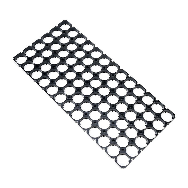
The 38121 6x13 Plastic Battery Cell Mounting Bracket is a purpose-designed mechanical component for organizing cylindrical battery cells inside custom battery modules, battery packs, energy storage assemblies, electric mobility systems, and other multi-cell power applications. Developed around a structured 6x13 cell arrangement, this type of mounting bracket provides a stable framework for positioning cylindrical cells while supporting insulation, mechanical separation, thermal planning, electrical interconnection, and enclosure integration.
In modern battery pack construction, the mechanical organization of individual cells is just as important as the electrical architecture. A large number of cylindrical cells must remain correctly positioned throughout assembly and operation. If cells move, rotate, tilt, or become unevenly distributed, subsequent operations such as insulation, interconnection, BMS installation, enclosure assembly, and thermal management can become more difficult. A dedicated plastic battery Cell Mounting Bracket provides a repeatable physical reference that helps create a more controlled battery module.
Material selection is a particularly important consideration for battery cell holders. Depending on the application, flame-retardant ABS, ABS+PC blends, PC, PA66, or other engineering polymers may be selected to provide a suitable combination of mechanical strength, dimensional stability, electrical insulation, temperature resistance, and flame-retardant performance. For demanding power and energy-storage applications, a UL94 V-0 flame-retardant grade may be specified when the material and final molded component have been appropriately tested and certified for that grade.
The use of a flame-retardant material can improve the fire behavior of the holder. It should not, however, be interpreted as a guarantee that a battery pack cannot experience thermal runaway. Thermal runaway is a complex electrochemical and thermal event influenced by cell chemistry, cell condition, charging conditions, electrical faults, mechanical damage, thermal propagation, protection circuitry, and enclosure design. A flame-retardant holder is therefore one part of a broader battery safety strategy.
The 38121 6x13 Plastic Battery Cell Mounting Bracket can be designed for applications where accurate cell positioning, repeatable layout, material safety, and flexible pack construction are required. Depending on the specific design, the bracket may be used as a single positioning component or as part of a paired upper-and-lower holder structure that captures both ends of cylindrical cells.
Customization is also an important consideration. Battery pack designers may require special-shaped holders, custom cell layouts, numbered positions, cable routing slots, sensor channels, fastening features, alignment points, or enclosure interfaces. Custom molding can accommodate application-specific requirements when standard configurations do not provide the necessary mechanical geometry.
Understanding the 38121 6x13 Configuration
The product designation 38121 6x13 Plastic Battery Cell Mounting Bracket combines a cell-format reference with a layout reference.
The 38121 designation identifies the intended cylindrical battery cell format or size family. The exact cell dimensions should always be confirmed against the actual cell manufacturer's drawing because nominal cell designations do not necessarily guarantee identical external dimensions across all suppliers and cell constructions.
The 6x13 designation generally indicates a matrix arrangement consisting of six positions in one direction and thirteen positions in another direction. This creates a structured physical layout for a multi-cell battery assembly.
The physical arrangement should not be confused with the electrical series-parallel configuration.
For example, a holder may contain a specific number of physical cell positions while the electrical architecture could use different series and parallel groupings depending on the battery system. Physical layout, electrical topology, voltage, capacity, current capability, and BMS architecture must therefore be evaluated separately.
A professional battery pack specification should identify at least:
Cell model
Actual cell diameter
Actual cell length
Number of cell positions
Physical arrangement
Cell orientation
Electrical series count
Electrical parallel count
Required holder structure
Material grade
Flame-retardant requirement
Insulation requirements
Thermal requirements
Enclosure dimensions
Customization requirements
This approach reduces ambiguity between mechanical and electrical specifications.
Why Battery Cell Mounting Brackets Matter
Cylindrical battery cells are inherently easy to move because their outer geometry is generally round. When dozens or hundreds of cells are placed together, uncontrolled movement can create assembly challenges.
A battery cell mounting bracket establishes a defined mechanical relationship between individual cells.
This can provide benefits such as:
Consistent cell positioning
Reduced lateral movement
Controlled cell spacing
Easier pack assembly
Improved internal organization
Better alignment for interconnections
More predictable enclosure dimensions
Easier insulation placement
Simplified thermal planning
Improved inspection access
The mounting bracket does not independently make a battery pack safe. Instead, it provides the mechanical framework needed for the other battery components to perform effectively.
A well-organized cell layout can make it easier to identify electrical connection points and reduce the chance of accidental misplacement during assembly.
Material Selection for Battery Cell Holders
Material selection is one of the most important technical decisions when developing a plastic battery cell mounting bracket.
A battery holder operates inside an environment where electrical insulation, mechanical stability, heat exposure, and long-term dimensional performance may all be important.
Common engineering considerations include:
Mechanical strength: The material must withstand insertion, handling, assembly, and normal mechanical loads without excessive deformation.
Dimensional stability: Cell openings need to remain within acceptable dimensional limits during normal operating conditions.
Temperature resistance: The material should be compatible with the expected environmental and operating temperature range.
Electrical insulation: Suitable polymers can provide electrical separation between mechanical structures and conductive components, although dedicated insulation may still be required.
Flame-retardant performance: For higher-risk power and energy-storage applications, an appropriate flame-retardant material grade may be required.
Impact resistance: Battery assemblies can experience vibration and mechanical shock, especially in mobile equipment.
Chemical resistance: The material may need to withstand exposure to oils, cleaning agents, humidity, or other environmental factors depending on the application.
ABS+PC for Battery Pack Applications
An ABS+PC blend combines characteristics of acrylonitrile butadiene styrene and polycarbonate.
The blend can be engineered to provide a balance of:
Mechanical strength
Impact resistance
Dimensional stability
Processability
Electrical insulation
Heat resistance
Surface quality
For battery applications, an appropriately formulated flame-retardant ABS+PC grade may provide additional resistance to ignition and flame propagation compared with ordinary non-flame-retardant plastics.
The exact performance depends on the resin formulation, additives, processing conditions, wall thickness, component geometry, and certification status.
Therefore, it is important to specify the actual resin grade rather than simply stating "ABS+PC."
A battery pack specification may need to identify:
Base polymer
Flame-retardant grade
UL94 classification
Operating temperature range
Color
Reinforcement
Impact performance
Electrical properties
Certification requirements
UL94 V-0 Flame Retardancy
For battery holder applications, UL94 V-0 is a commonly requested flame-retardant classification.
UL94 is a plastics flammability testing system used to characterize the burning behavior of polymeric materials under defined laboratory conditions.
A V-0 classification indicates a higher level of vertical burning performance than lower classifications such as V-1 or V-2 under the applicable test conditions.
This distinction is important because standard ABS without an appropriate flame-retardant formulation may only achieve a lower flammability classification such as HB, depending on the specific material.
When a battery holder is intended for high-power or energy-storage applications, specifying the desired flame-retardant grade can help prevent misunderstandings during material selection and sourcing.
The material requirement should therefore be written clearly.
For example:
Required material: Flame-retardant ABS+PC
Required classification: UL94 V-0
Application: Battery module or energy-storage assembly
The exact certification should be verified against the specific material grade and molded component. A generic statement that a plastic is "flame retardant" is not sufficient when a project requires a particular UL94 rating.
Flame Retardancy and Battery Safety
Flame-retardant plastic can improve the fire resistance characteristics of a battery holder, but it does not eliminate the possibility of thermal events.
Battery thermal runaway can result from various causes, including:
Internal cell defects
Overcharging
External short circuits
Excessive current
Mechanical damage
Elevated temperatures
Manufacturing defects
Cell aging
Improper electrical configuration
Inadequate protection
During a serious battery failure, the heat generated by a cell can exceed the thermal resistance of many surrounding materials.
For this reason, a UL94 V-0 holder should be viewed as a supporting component in a larger safety system.
A complete battery safety architecture may involve:
Suitable cell selection
Cell matching
BMS protection
Overcurrent protection
Fusing
Temperature monitoring
Electrical insulation
Thermal management
Mechanical protection
Flame-resistant materials
Appropriate enclosure design
Fault detection
Proper charging control
The holder contributes to the mechanical and material safety portion of this architecture.
Heat Resistance
Battery holders may operate near heat-producing components.
Heat can originate from:
High-current cells
Busbars
Power electronics
Charging components
MOSFETs
Connectors
Motors
Inverters
Resistors
Thermal transfer structures
Material selection should therefore be based on the highest expected temperature rather than average operating temperature alone.
ABS+PC can be suitable for many general battery applications when an appropriate grade is selected. However, areas exposed to higher temperatures may require a higher-performance polymer.
For demanding locations, PC or PA66 may be considered when their specific properties better match the working environment.
The exact material should be selected based on actual thermal data rather than simply choosing a material by name.
ABS, PC, and PA66 Material Selection
Different applications require different polymer characteristics.
Flame-retardant ABS can be suitable for general battery PACK assemblies where moderate temperature exposure and good processability are required.
Potential advantages include:
Good molding performance
Good dimensional control
Balanced mechanical properties
Cost-effective production
Available flame-retardant grades
Good surface finish
Polycarbonate can provide higher heat resistance and strong impact performance compared with many standard plastics.
It may be considered for:
Areas near heat sources
Higher-temperature battery structures
Electrical insulation components
Components requiring strong impact resistance
PA66 can provide high mechanical strength and useful temperature performance.
It may be considered for:
Higher mechanical loads
Higher-temperature environments
Structural battery components
Applications where rigidity and heat resistance are important
The appropriate polymer should be selected based on the complete operating environment.
Material Selection Based on Working Conditions
There is no single plastic material that is ideal for every battery pack.
A practical selection process begins with the working environment.
For general battery PACK assemblies, a flame-retardant ABS grade may provide a suitable balance of cost, processability, mechanical performance, and flame resistance.
For locations close to significant heat sources, PC or PA66 may be more appropriate depending on the temperature, load, chemical environment, and mechanical requirements.
For specialized applications, other engineering polymers may also be considered.
The material selection process should evaluate:
Maximum temperature
Continuous temperature
Short-duration temperature
Mechanical stress
Vibration
Impact
Electrical voltage
Insulation requirements
Humidity
Chemical exposure
Flame-retardant classification
Manufacturing process
Cell Model and Layout Specification
Clear product identification is essential when ordering or designing battery holders.
A vague specification such as "battery holder" is often insufficient.
A more useful specification identifies the cell format, arrangement, and holder architecture.
For example:
Cell model: 18650
Layout: 4-parallel 5-series
Cell quantity: 20 cells
Holder design: Upper-lower paired structure
This type of description gives the mechanical supplier a clearer understanding of the intended configuration.
For the 38121 6x13 product, the specification should similarly identify the intended 38121 cell dimensions and the six-by-thirteen physical layout.
The final documentation should distinguish between:
Physical cell count
Electrical cell count
Series groups
Parallel groups
Holder position count
This is particularly important when multiple battery pack versions use similar cell formats.
Physical Layout Versus Electrical Configuration
A mounting bracket describes the physical arrangement of cells.
Electrical configuration describes how those cells are connected.
These are related but different specifications.
For example, a physical holder can contain a regular matrix while electrical connections are routed according to a separate series-parallel design.
The electrical architecture determines:
Voltage
Capacity
Current capability
Charging voltage
BMS configuration
The physical architecture determines:
Cell position
Mechanical dimensions
Spacing
Orientation
Structural arrangement
Keeping these specifications separate makes battery design documentation more accurate.
Upper-Lower Paired Holder Structure
One common battery holder structure uses two matching components.
An upper holder can position one end of the cylindrical cells, while a lower holder positions the opposite end.
Together, the two components can form a more stable mechanical assembly.
This design may offer:
Better cell retention
Improved alignment
More stable pack geometry
Reduced cell movement
Easier module handling
Better structural consistency
The actual design depends on the cell geometry and intended battery pack.
For cylindrical cells, an upper-and-lower configuration can be particularly useful when the pack must withstand vibration or transportation.
Single-Side Positioning Structure
Not every application requires paired holders.
Some battery assemblies may use a single-side positioning bracket.
A single-side structure can provide:
Basic cell alignment
Simplified assembly
Reduced component count
Lower structural complexity
Easier access to the opposite end of cells
However, whether single-side positioning is sufficient depends on the enclosure, cell movement requirements, pack orientation, vibration environment, and additional mechanical support.
When requesting a custom holder, the customer should clearly specify whether an upper-and-lower pair is required or whether single-side positioning is acceptable.
Confirming Holder Structure Before Production
Before mold development or mass production, several mechanical details should be confirmed.
These include:
Number of cell positions
Cell model
Cell diameter
Cell length
Cell orientation
Upper holder requirement
Lower holder requirement
Single-side or double-side positioning
Overall holder dimensions
Cell spacing
Mounting holes
Fastening points
Cable channels
Sensor channels
Identification marks
Clear technical documentation reduces the possibility of tooling revisions.
Custom Mold-Making
Custom mold-making is useful when a standard battery holder cannot meet the mechanical requirements of a specific battery pack.
A custom mold can be developed for:
Special-shaped battery holders
Unusual cell arrangements
Irregular enclosure geometries
Custom mounting interfaces
Numbered cell positions
Cable routing channels
Sensor channels
Fastener locations
Snap-fit structures
Alignment features
Custom tooling can provide a more integrated solution than modifying a standard holder.
However, mold development generally involves higher initial engineering and tooling costs compared with purchasing an existing standard design.
Special-Shaped Battery Holders
Not all battery packs use simple rectangular arrangements.
Some applications require irregular layouts because of enclosure limitations.
For example, a battery pack may need to fit around:
Motors
Control boards
Structural frames
Cooling components
Curved housings
Mounting brackets
Wiring assemblies
A custom molded holder can be designed around these constraints.
Special-shaped battery holders can help maximize available internal space while maintaining organized cell positioning.
Numbered Cell Marking
Numbered markings can be incorporated into customized battery holders.
Numbering can assist with:
Assembly instructions
Cell identification
Electrical connection mapping
Quality inspection
Service procedures
Production traceability
For example, individual positions can be marked with sequential numbers to indicate cell locations.
This can reduce assembly mistakes when the battery contains a large number of cells.
Marking can also help technicians follow a predetermined wiring or BMS connection plan.
Cable Routing Slots
Cable routing slots are another useful customization feature.
Battery packs may contain:
BMS wires
Temperature sensor wires
Balance leads
Power cables
Communication cables
Connector wires
Without planned routing, cables may interfere with cell positioning or become compressed between structural components.
Integrated cable routing slots can provide a more organized pathway.
Potential benefits include:
Cleaner internal layout
Reduced cable movement
Better wire organization
Improved assembly efficiency
Easier maintenance
Reduced mechanical interference
The routing structure should be designed according to actual wire diameter and bend radius.
BMS Integration
The battery management system is an important part of many rechargeable battery assemblies.
A mounting bracket can provide the mechanical framework needed to organize cells while leaving appropriate space for BMS wiring.
The BMS may monitor:
Cell voltage
Pack voltage
Current
Temperature
Charging state
Discharging conditions
The holder itself does not provide these electronic functions.
However, a well-designed holder can simplify BMS installation by creating a predictable physical layout.
Thermal Sensor Channels
Custom holders may incorporate dedicated sensor positioning features.
Temperature sensors can be placed at locations selected by the thermal design team.
Potential considerations include:
Central cells
High-current zones
Heat-generating regions
Areas near power electronics
Cooling interfaces
A sensor channel can prevent wires from being pinched and help maintain a consistent sensor position.
The actual sensor location should be determined by testing and thermal analysis.
Mechanical Strength
The holder must withstand the mechanical stresses associated with battery assembly.
Potential stresses include:
Cell insertion force
Cell removal force
Pack handling
Vibration
Shock
Enclosure compression
Thermal expansion
Transportation
A suitable polymer and wall geometry can provide the necessary rigidity.
The final mechanical strength depends on:
Material
Wall thickness
Rib structure
Cell opening design
Mold design
Processing quality
Temperature
Load direction
Therefore, a generic material statement should not be treated as a complete mechanical specification.
Dimensional Accuracy
Dimensional accuracy is essential for battery cell mounting brackets.
Small dimensional differences can influence:
Cell fit
Cell spacing
Pack width
Pack height
Enclosure compatibility
Electrical connection alignment
Injection molding can provide repeatable dimensions when the mold, material, processing parameters, and quality control are properly managed.
Critical dimensions should be identified on the technical drawing.
These may include:
Cell opening diameter
Center-to-center distance
Overall length
Overall width
Holder height
Mounting hole diameter
Alignment feature dimensions
Cell Tolerance and Holder Tolerance
The holder should be designed with the actual tolerance range of the battery cell in mind.
Battery cells can vary slightly in diameter and length due to manufacturing tolerances, protective sleeves, labels, and construction differences.
If the holder opening is designed only around the nominal cell diameter, some cells may fit too tightly while others may fit too loosely.
A proper engineering approach considers the tolerance stack.
This can improve:
Assembly consistency
Cell retention
Serviceability
Production yield
Mechanical reliability
Electrical Insulation
Plastic battery holders can provide a useful level of mechanical separation, but electrical insulation should be evaluated separately.
Additional insulation may be required around:
Positive terminals
Negative terminals
Nickel strips
Busbars
Welding points
Conductive fasteners
BMS wiring
Enclosure walls
Common Insulation Materials include:
PET film
PC film
Fish paper
Aramid paper
Polyimide tape
Insulating washers
The exact insulation architecture depends on the battery design.
High-Voltage Insulation Considerations
For higher-voltage battery assemblies, insulation requirements become more demanding.
A plastic holder may contribute to electrical separation, but dielectric performance depends on:
Material formulation
Thickness
Geometry
Surface contamination
Humidity
Creepage distance
Clearance distance
Applied voltage
Temperature
Therefore, "high-voltage insulation" should be specified through measurable engineering requirements rather than used as a generic marketing phrase.
When required, designers should establish appropriate dielectric, creepage, and clearance requirements for the complete battery assembly.
Creepage and Clearance
Creepage is the shortest path along an insulating surface between conductive parts.
Clearance is the shortest distance through air between conductive parts.
Battery holders can influence both because their geometry determines how conductive components are physically positioned.
For higher-voltage systems, the holder design should avoid creating unnecessarily short conductive paths.
Custom holder geometry can be developed to provide appropriate separation around:
Busbars
Terminals
Connectors
Power leads
Cell groups
The actual required distances depend on voltage, environment, insulation system, pollution level, applicable standards, and system design.
Thermal Management and Holder Design
Thermal management should be considered during holder development rather than after the mechanical design is complete.
The holder geometry can influence:
Airflow
Cell spacing
Contact surfaces
Cooling plate integration
Sensor placement
Heat transfer pathways
In some battery modules, the holder may be intentionally designed with openings or channels to permit air movement.
In liquid-cooled systems, the holder may need to accommodate cooling plates or thermal interfaces.
The ideal structure depends entirely on the battery architecture.
Heat Sources Near Battery Holders
A holder positioned near heat sources requires careful material selection.
Potential heat sources include:
High-current busbars
Power semiconductors
Charging electronics
Inverters
DC converters
Motors
Resistors
Transformer components
When the holder is located near these components, a standard material may not provide sufficient temperature margin.
This is one reason PC or PA66 may be considered for demanding areas.
Material selection should use measured or calculated temperature conditions rather than assumptions.
Flame Retardancy for ESS Applications
Energy Storage Systems can contain a substantial amount of stored energy.
For ESS applications, material selection should therefore be considered at the module and system level.
A flame-retardant battery holder can contribute to improved material behavior during a localized thermal event.
However, ESS safety requires multiple layers of protection, potentially including:
Cell monitoring
Module monitoring
BMS
Thermal sensors
Fuses
Contactors
Fire detection
Thermal barriers
Ventilation
Enclosure protection
System controls
A UL94 V-0 material classification is only one material-level property.
Flame Retardancy for Electric Vehicle Battery Packs
Electric vehicle battery packs experience demanding conditions including vibration, temperature variation, high current, mechanical shock, and long operating cycles.
A suitable battery cell holder can help maintain stable cell geometry while a flame-retardant polymer may provide improved resistance to ignition and flame propagation.
EV battery structures typically require comprehensive consideration of:
Mechanical integrity
Crash conditions
Electrical insulation
Thermal propagation
Cell monitoring
Water protection
Dust protection
High-voltage safety
Enclosure strength
The mounting bracket is therefore one component in a much larger engineered system.
Battery Pack Assembly Process
A typical battery pack assembly using a mounting bracket may involve several stages.
First, the cell model and actual dimensions are confirmed.
Next, the mounting bracket is inspected for dimensional accuracy and physical defects.
The cells are then positioned according to the specified physical layout.
The required insulation is installed.
Electrical interconnections are prepared according to the approved design.
BMS components and sensors are positioned.
The assembly is placed into its enclosure or module structure.
Mechanical retention is then completed.
Finally, the complete battery system undergoes appropriate inspection and testing.
The exact process varies according to battery chemistry, cell type, pack design, and manufacturing method.
Quality Inspection of Plastic Battery Holders
Quality inspection should address both appearance and dimensions.
Visual inspection may check for:
Cracks
Warping
Flash
Burrs
Short shots
Sink marks
Surface damage
Contamination
Incomplete molding
Dimensional inspection may check:
Cell opening diameter
Center spacing
Overall dimensions
Mounting features
Alignment features
Holder thickness
For flame-retardant applications, material documentation and certification should also be verified.
Injection Molding Considerations
Injection molding is widely used for producing repeated plastic battery holder geometries.
Important molding parameters can include:
Resin drying
Melt temperature
Mold temperature
Injection pressure
Holding pressure
Cooling time
Mold design
Gate position
Ejection design
For flame-retardant materials, processing conditions can affect final component properties.
The molded component should therefore be produced according to the resin manufacturer's processing recommendations.
Mold Design
A custom mold for a 38121 6x13 holder may require detailed consideration of:
Cell opening geometry
Wall thickness
Ribs
Snap-fit features
Draft angles
Ejection points
Gates
Cooling channels
Parting lines
Numbering marks
Cable slots
Mounting interfaces
Good mold design can improve dimensional consistency and production efficiency.
Customization Options
A customized 38121 6x13 battery cell mounting bracket can potentially include:
Custom cell spacing
Modified cell openings
Special outer dimensions
Numbered cell positions
Cable routing slots
Sensor channels
Mounting holes
Snap-fit features
Screw bosses
Alignment pins
Upper-lower paired structures
Single-side positioning
Special-shaped layouts
Custom colors
Material changes
The available options depend on the mold and production method.
MOQ Considerations
Custom molded battery holders generally require tooling investment.
For this reason, customized production often has a higher minimum order quantity than standard off-the-shelf components.
A typical custom project may involve a minimum order quantity ranging from several hundred to approximately one thousand sets, depending on:
Mold complexity
Material
Part size
Production process
Customization level
Manufacturing economics
The exact MOQ should be confirmed during quotation because it is not a universal industry standard.
Prototype Before Mass Production
For a customized battery holder, prototype validation is highly recommended before committing to large-volume production.
Prototype testing can evaluate:
Cell insertion
Cell retention
Dimensional fit
Holder alignment
Upper-lower engagement
Cable routing
Sensor placement
Enclosure compatibility
Assembly time
Prototype evaluation can identify design problems before final mold production.
Battery Pack Enclosure Integration
The holder must fit within the overall enclosure.
Important dimensions include:
Overall pack length
Overall pack width
Overall pack height
Holder thickness
Cell length
Insulation thickness
Wiring space
BMS space
Cooling space
The battery holder should not be designed independently from the enclosure.
A complete 3D mechanical model can help identify interference before tooling.
Vibration and Shock
Mobile battery applications may experience vibration and shock.
Examples include:
E-bikes
Electric vehicles
Power tools
Robotics
Portable equipment
The mounting bracket can help limit cell movement, but the complete system should also include suitable mechanical support.
Testing may evaluate:
Cell retention
Holder cracking
Cell movement
Wiring damage
Connector stability
Enclosure integrity
Moisture and Environmental Exposure
Battery holders used in outdoor equipment may experience humidity, condensation, dust, or water exposure.
Material selection should consider the actual environment.
The holder alone does not provide complete waterproofing.
A complete waterproof battery design may require:
Sealed enclosure
Gaskets
Cable glands
Waterproof connectors
Conformal protection where appropriate
Drainage strategy
The polymer holder is only one part of the environmental protection system.
Chemical Compatibility
The holder may come into contact with various substances during manufacturing or use.
Potential exposures include:
Cleaning agents
Oils
Greases
Adhesives
Sealants
Battery-related contaminants
The selected polymer should be checked for chemical compatibility with the actual substances involved.
Storage of Plastic Battery Holders
Plastic holders should be stored in conditions appropriate for their material.
General considerations include:
Avoid direct sunlight
Avoid excessive heat
Avoid unnecessary moisture
Prevent deformation
Keep away from aggressive chemicals
Avoid heavy stacking loads
Flame-retardant materials should be stored according to supplier recommendations.
Transportation
During transportation, plastic holders should be protected from:
Crushing
Bending
Excessive impact
Contamination
High temperatures
If the holder is shipped together with battery cells, the transportation requirements become substantially more complex because batteries are regulated products in many jurisdictions.
The mechanical holder does not determine the transportation classification of the battery.
Sustainable Battery Pack Design
Material efficiency can also be considered during holder development.
A well-designed bracket may reduce unnecessary plastic usage while maintaining adequate structural performance.
Potential design strategies include:
Optimized wall thickness
Reinforcement ribs
Material-efficient geometry
Modular construction
Reusable structural components
However, reducing material should never compromise required mechanical or flame-retardant performance.
Why Custom Cell Layouts Are Important
Battery manufacturers and system integrators often need battery packs that fit unique spaces.
A standard rectangular holder may not always match the available enclosure.
Custom layouts can help accommodate:
Irregular housings
Vehicle structures
Portable equipment
Robotics
Industrial machinery
Compact energy storage systems
The 38121 6x13 concept can therefore serve as a foundation for both standardized and customized battery mechanical designs.
Advantages of a 38121 6x13 Plastic Battery Cell Mounting Bracket
The principal advantages can be summarized as follows:
Structured cell positioning: Provides defined positions for cylindrical cells.
Precision molding: Supports repeatable geometry and consistent assembly.
Flame-retardant material options: Suitable flame-retardant grades can be selected for demanding applications.
UL94 V-0 option: A V-0 material specification can be requested where the application requires this classification.
Electrical insulation support: Engineering plastics can contribute to mechanical and electrical separation.
Heat resistance options: Material selection can be adapted to different operating environments.
Modular structure: Can support upper-lower paired or single-side positioning designs.
Customization: Special layouts, markings, channels, and mounting features can be developed.
Industrial suitability: Appropriate for custom battery modules, ESS, electric mobility, power equipment, and other applications.
Comparison of Common Holder Structures
An upper-lower paired structure secures both ends of the cylindrical cells.
This approach is useful when:
High mechanical stability is required
The pack experiences vibration
Cell movement must be minimized
A fixed module structure is desired
A single-side holder positions one end of the cells.
This approach can be useful when:
The enclosure provides additional support
Lower component count is preferred
Easy access is required
Mechanical loads are relatively moderate
A custom holder can combine several functions.
It may include:
Cell positioning
Cable routing
Sensor channels
Mounting features
Numbering
Alignment features
This can create a more integrated battery module structure.
Selecting the Right Material Grade
The correct material should be selected based on actual working conditions.
For a general battery PACK:
Flame-retardant ABS may provide a balanced solution.
For areas exposed to higher heat:
PC may be considered.
For demanding mechanical and thermal environments:
PA66 may be considered.
For applications requiring a specific flame rating:
UL94 V-0 flame-retardant grade should be explicitly specified.
The actual choice should be validated using material data sheets and application testing.
Product Specification Checklist
When requesting or purchasing a 38121 6x13 battery holder, the technical specification should ideally include:
Cell model: 38121
Physical layout: 6x13
Cell quantity: Confirm according to the holder design
Material: ABS+PC, ABS, PC, PA66, or specified engineering polymer
Flame rating: UL94 V-0 where required
Holder structure: Upper-lower paired or single-side
Cell opening: Matched to actual cell dimensions
Cell spacing: Application-specific
Mounting method: Application-specific
Cable routing: Standard or customized
Numbering: Standard or customized
Sensor channels: Optional according to design
Color: Application-specific
Custom mold: Available for special structures where production conditions permit
MOQ: Project-dependent, commonly several hundred to approximately one thousand sets for customized production
Technical Specification Notes
Exact dimensions should always be taken from the final engineering drawing.
Important dimensions may include:
Cell hole diameter
Cell center distance
Row spacing
Column spacing
Overall length
Overall width
Holder height
Wall thickness
Mounting hole size
Cable slot dimensions
Sensor channel dimensions
Because different 38121 cells can have different mechanical tolerances, the actual cell drawing should be used during holder development.
Product Description for Industrial Catalogs
The 38121 6x13 Plastic Battery Cell Mounting Bracket is a precision-molded Cylindrical Battery Holder designed for structured multi-cell battery pack assembly. Its 6x13 positioning layout provides a stable mechanical framework for compatible 38121 cylindrical cells while supporting consistent spacing, organized cell alignment, and efficient module construction.
For demanding applications, flame-retardant ABS+PC materials can be specified with a UL94 V-0 grade, providing improved flame resistance compared with standard non-flame-retardant plastic grades. Material selection can be adapted to the working environment, with flame-retardant ABS suitable for many general PACK applications and PC or PA66 considered for areas exposed to higher temperatures or demanding mechanical conditions.
The holder can be designed as an upper-and-lower paired structure or a single-side positioning component, depending on the battery module architecture. Custom molding can also accommodate special-shaped battery holders, numbered cell positions, cable routing slots, sensor channels, mounting features, and application-specific geometries.
The 38121 6x13 Plastic Battery Cell Mounting Bracket is suitable for custom battery packs, energy storage systems, electric vehicle battery modules, power equipment, portable energy systems, robotics, and other cylindrical-cell applications where stable mechanical positioning and engineered polymer construction are required.
Applications
The holder can be integrated into battery modules for energy storage applications where large numbers of cylindrical cells must be mechanically organized.
For electric mobility systems, a structured cell holder can help maintain cell positioning under vibration and mechanical movement.
Compact power equipment can benefit from organized cylindrical cell arrangements that fit within confined housings.
Portable energy systems require a combination of compact packaging, mechanical stability, electrical insulation, and thermal planning.
Robotic systems often experience repeated acceleration, vibration, and movement, making cell retention important.
Industrial equipment can use customized mounting structures to create repeatable battery module architectures.
The holder can also support custom battery prototypes where a defined cell layout is preferred over loose cell arrangements.
Common Technical Questions
It is a molded plastic mechanical holder designed to position compatible 38121 cylindrical battery cells in a six-by-thirteen physical layout.
It helps establish consistent cell positions, supports mechanical separation, simplifies assembly, and provides a structural framework for the battery module.
Material choice depends on working conditions. Flame-retardant ABS, ABS+PC, PC, PA66, and other engineering polymers may be suitable depending on temperature, mechanical, electrical, and flame-retardant requirements.
UL94 V-0 is a recognized flame-retardant classification for plastics under specified test conditions. It may be requested for applications where improved flame behavior is required.
No. Standard ABS may not provide the required flame-retardant classification or temperature performance for demanding battery applications.
PC or PA66 may be considered when the holder is exposed to higher temperatures, greater mechanical loads, or other demanding working conditions, subject to the specific material grade.
No. UL94 V-0 describes the burning behavior of a material under specified test conditions. It does not prevent battery thermal runaway.
A suitable plastic can contribute to electrical insulation, but the complete battery system must be designed according to the required voltage, creepage, clearance, dielectric, and environmental requirements.
Not always. The appropriate structure depends on the enclosure, vibration level, cell arrangement, and mechanical retention requirements.
Yes, custom designs can potentially include special-shaped structures, numbering, cable routing slots, sensor channels, mounting features, and modified cell layouts.
Custom molded production commonly requires several hundred to approximately one thousand sets, although the actual MOQ depends on tooling, material, geometry, and production economics.
Recommended Customization Request Format
For efficient technical communication, a customization request can contain the following information:
Cell Model: 38121
Cell Dimensions: Actual diameter and length
Physical Layout: 6x13
Electrical Configuration: Specify series and parallel architecture separately
Holder Type: Upper and lower pair or single-side holder
Material: ABS+PC, flame-retardant ABS, PC, PA66, or another required material
Flame Rating: UL94 V-0 if required
Operating Temperature: Specify expected range
Cable Routing: Required or not required
Number Marking: Required or not required
Sensor Channel: Required or not required
Mounting Features: Specify screw holes, clips, brackets, or other interfaces
Special Geometry: Provide drawings or 3D data where applicable
Quantity: Prototype quantity and target production quantity
This format makes it easier to evaluate tooling requirements and production feasibility.
Design Validation
Before mass production, the complete holder design should be validated.
Important tests can include:
Cell fit testing
Cell insertion testing
Cell removal testing
Dimensional verification
Mechanical retention testing
Vibration testing
Thermal exposure testing
Insulation verification
Flame performance verification where applicable
Enclosure integration testing
The test program should be based on the intended application.
Quality and Reliability
Long-term reliability depends on the interaction between material, geometry, cells, enclosure, thermal environment, and mechanical loads.
A high-quality holder should maintain:
Consistent cell positioning
Stable mechanical geometry
Appropriate material performance
Reliable retention
Controlled dimensions
Good molding quality
A battery holder should not be evaluated solely by visual appearance. Material documentation, dimensional inspection, functional testing, and application validation can provide a more reliable assessment.
Engineering Considerations for Large Battery Packs
As the number of cells increases, mechanical organization becomes increasingly important.
Large battery modules may contain many repeated cell groups. A standardized mounting structure can provide:
Repeatable cell geometry
Consistent assembly
Easier inspection
Better module organization
Simplified enclosure design
More predictable thermal planning
For large energy storage applications, multiple holder modules can potentially be integrated into a larger battery architecture.
Integration With Thermal Barriers
In applications where thermal propagation is a concern, additional thermal barriers may be incorporated into the battery module.
Possible components include:
Flame-retardant films
Insulating barriers
Thermal insulation sheets
Ceramic-based barriers
Mica-based materials
Aramid insulation
Specialized thermal management components
The mounting bracket can be designed to coexist with these components.
Integration With Cushioning Materials
Cushioning materials may be used between the holder, cells, and enclosure.
Potential functions include:
Vibration absorption
Shock reduction
Gap filling
Mechanical support
Noise reduction
EVA foam, rubber, silicone, and other cushioning materials may be selected according to temperature and environmental requirements.
The compatibility of cushioning material with the battery operating environment should always be checked.
Packaging Efficiency
A carefully designed cell holder can improve the efficiency of internal battery packaging.
Consistent cell positions can reduce unnecessary gaps and make the available enclosure volume easier to use.
This can be particularly important for:
Portable power systems
Electric vehicles
E-bike batteries
Power tools
Robotics
However, packaging density should never be increased at the expense of required thermal, electrical, or mechanical clearances.
Assembly Efficiency
A defined cell holder can reduce manual positioning work.
During assembly, workers can place cells into predetermined positions rather than manually aligning every cell.
This can improve:
Assembly consistency
Production speed
Inspection efficiency
Repeatability
Training simplicity
Numbered positions can further support standardized production procedures.
Serviceability
A modular battery holder can also support service and inspection.
If the pack architecture allows disassembly, technicians may be able to inspect:
Cell position
Holder condition
Wiring
Insulation
Sensor routing
Mechanical fastening
Serviceability depends on the complete enclosure and battery architecture.
Final Technical Perspective
The 38121 6x13 Plastic Battery Cell Mounting Bracket is a mechanical battery-pack component designed to provide controlled positioning and structural organization for cylindrical cells. Its value comes from combining accurate cell placement with material selection appropriate for the operating environment.
For general battery PACK construction, flame-retardant ABS can offer a practical balance of cost and performance. For applications demanding a stronger combination of heat resistance, impact performance, and electrical insulation, ABS+PC, PC, or PA66 may be considered according to the actual requirements.
For power and energy-storage applications where flame performance is a specified requirement, a UL94 V-0 flame-retardant material grade should be clearly identified in the technical specification. This is more precise than simply requesting "flame-retardant plastic."
The holder structure should also be explicitly defined. An upper-and-lower paired design provides support at both ends of the cylindrical cells, while a single-side design may be sufficient when the enclosure or other mechanical components provide additional retention.
Clear communication of the cell model, physical layout, electrical configuration, material grade, flame rating, holder structure, and customization requirements is essential before production.
Custom mold-making can provide additional flexibility for specialized battery modules. Numbered cell positions, cable routing slots, sensor channels, custom mounting interfaces, and special-shaped layouts can be incorporated where technically and economically practical. Custom projects commonly involve minimum quantities ranging from several hundred to approximately one thousand sets, although actual requirements depend on the project.
The 38121 6x13 Plastic Battery Cell Mounting Bracket can therefore serve as a practical foundation for battery modules used in ESS, electric vehicles, power tools, portable power equipment, robotics, industrial systems, and custom battery projects.
A properly engineered battery holder does not operate independently. It works together with battery cells, electrical interconnections, BMS protection, insulation materials, thermal management components, enclosure structures, sensors, and mechanical supports. When these elements are designed as an integrated system, the cell mounting bracket can contribute significantly to organized, repeatable, and robust battery pack construction.
This website uses cookies to ensure you get the best experience on our website.


 Phone
Phone